Nice. What cutting tools are you using? And how do you cut the compound angles? I have done only 2.5D and some simple 3D on my CNC router. All g-code is made in F360? And the alignment? I would really appreciate some tips on how to make such an advanced project for my CNC. I would mostly need some tips on which tools and which machining strategies to use for the compound angles, that would really help me move forward. Pointing to a tutorial would be great, too. I use Estlcam and CamBam now, might try F360 for CAM as well.
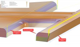
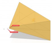
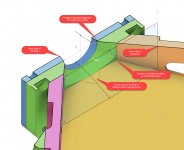
The compound angles on the lower horn were a bit of a trick to work out a good solution for. I ended up using a tapered bit (specs in attached screenshot) and a 3D contour toolpath.
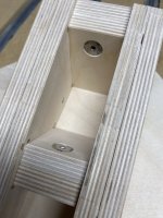
The design also requires that the parts be machined from two sides, as the tapers don't all face the same side of the stock. I drill 1/4" registration holes through the stock on side A and machine that side. Then flip the panel over, register the part using 1/4" pins, and machine side B.
This was actually the first time I've done a two-sided CNC project, so it was a great opportunity learn how to approach the process.
Attachments
Do you think I could make some more simple angles (like for example for a petal horn) with a ball mill?
Yes, I think a standard ball mill would be totally acceptable for this kind of work, as long as you don't have multiple tapers coming together and meeting at an angle less than 180 degrees (at which point the quality of the seam between them would be limited by the radius of the ball mill).
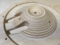
Got the cone filler carved today. In another slight departure from the baseline design, I made the filler disc a bit thicker (it comes in at 1.2 inches tall). The profile conforms more closely to the measured profile of the LF driver cone, while still leaving the required gap for full cone excursion.
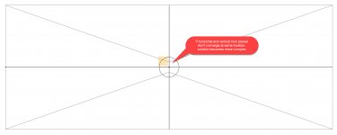
The section view in Fusion360 was really helpful when working on this feature. The screen shot below shows an approximation of the speaker cone; the cone filler disc is based on the cone measurements posted by Jennygirl in this thread.
The journey continues...
The section view in Fusion360 was really helpful when working on this feature. The screen shot below shows an approximation of the speaker cone; the cone filler disc is based on the cone measurements posted by Jennygirl in this thread.
The journey continues...
Attachments
Last edited:
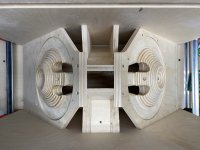
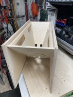
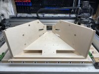
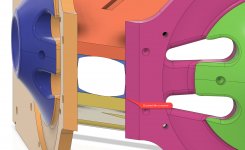
A few more progress pics. It's starting to come together.
Today I dry fit the primary horn and thankfully it all snapped together nicely. I think if I build a second one, I will add a bit more clearance in the dado slots for the pole box. The wood glue adds enough thickness that my .005" clearance is a bit tight in that area.
I'm thankful I took the time to add the dado slots and pre-tap the pilot holes on the CNC. It really makes getting all the horn angles lined up much easier. I don't know that I have the necessary skill to assemble this without the assistance of those features. This is my first DIY speaker build and it is not exactly a beginner-level project. I have gained a lot of respect for Art and the others who have built this before me.
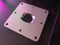
Next up is the throat adapter plate. The plan is to mill it from two pieces of 1/4" aluminum plate. We'll see how that goes - I've never tried doing any curved-surface milling in aluminum.
Patrick
Today I dry fit the primary horn and thankfully it all snapped together nicely. I think if I build a second one, I will add a bit more clearance in the dado slots for the pole box. The wood glue adds enough thickness that my .005" clearance is a bit tight in that area.
I'm thankful I took the time to add the dado slots and pre-tap the pilot holes on the CNC. It really makes getting all the horn angles lined up much easier. I don't know that I have the necessary skill to assemble this without the assistance of those features. This is my first DIY speaker build and it is not exactly a beginner-level project. I have gained a lot of respect for Art and the others who have built this before me.
Next up is the throat adapter plate. The plan is to mill it from two pieces of 1/4" aluminum plate. We'll see how that goes - I've never tried doing any curved-surface milling in aluminum.
Patrick
Attachments
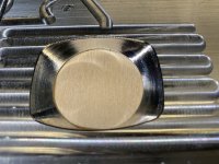
Small update. Did a test cut in some scrap aluminum to work out the settings for carving the throat adapter. Results are encouraging. The shaping was done with a 1/4" ball mill with 0.1mm passes. I'm thinking I can probably get away with 0.25mm passes to speed things up. This one took about 10 minutes on the CNC.
Attachments
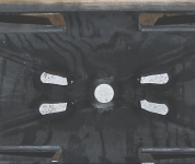
Rear adapter plate finished. Moving on to front adapter plate. I used a 1/4" ball mill with a 0.25mm stepdown for the curved surface milling. I think the surface finish turned out pretty decent for a hobby-level CNC router.
Attachments
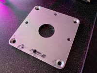
Pyronious,Rear adapter plate finished. Moving on to front adapter plate. I used a 1/4" ball mill with a 0.25mm stepdown for the curved surface milling. I think the surface finish turned out pretty decent for a hobby-level CNC router.
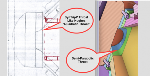
The milling looks great, but the throat you created is not what the SynTripP throat was designed as.
The SynTripP horn throat was made like the Hughes Quadratic throat, which is a simplification of Earl Geddes oblate spheroid throat transformation.
Page 8 of "The Quadratic-Throat Waveguide®:A White Paper On An Invention By Charles E. Hughes of Peavey Electronics Corporation" shows how it should be made if you would like it to perform as the original SynTripP does. The SynTripP coverage angles are not 30 degrees as in the Hughes depiction.
Art
Attachments
Last edited:
The SynTripP horn throat was made like the Hughes Quadratic throat, which is a simplification of Earl Geddes oblate spheroid throat transformation.
Page 8 of "The Quadratic-Throat Waveguide®:A White Paper On An Invention By Charles E. Hughes of Peavey Electronics Corporation" shows how it should be made if you would like it to perform as the original SynTripP does. The SynTripP coverage angles are not 30 degrees as in the Hughes depiction.
Thank you Art for noticing this. I would very much like to follow your design as accurately as I am able. The diagram showing the construction of the quadratic throat is very helpful. However I have a question about implementing the design for the SynTripP TAP.
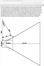
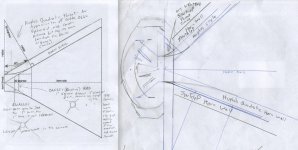
I sketched up a horizontal section of the horn, based on the dimensions you've given, and showing my current TAP profile. I then computed the proposed Hughes Quadratic profile.
The quadratic profile results in a circular input profile on the TAP that is 1.8" in diameter. This is 0.4" larger than the circular output on the compression driver. Will this present a problem? Do the "input" of the TAP and the "output" of the driver need to be the same diameter?
Thank you,
Patrick
Attachments
Patrick,The quadratic profile results in a circular input profile on the TAP that is 1.8" in diameter. This is 0.4" larger than the circular output on the compression driver. Will this present a problem? Do the "input" of the TAP and the "output" of the driver need to be the same diameter?
The TAP (Throat Adapter Plate) "input" side should match the driver throat diameter exactly.
The 2.3125" horn throat dimension appears too narrow to support a quadratic profile unless the TAP was made deeper, which may preclude the HF driver from fitting in the 15" cabinet depth.
Looking at my 2014 notes, the original SynTripP was not a "full" quadratic transition, as I believed it may cause some horizontal "beaming" above 10kHz.
The original SynTripP throat corners were rounded with Bondo-Glass putty and the transition from the 1.4" driver entrance hole to the horn walls were smoothed using a half-round file.
Art
Attachments
Thank you for the additional details, Art.
Yes, I only have 0.7" to spare between the HF driver and the rear panel. I already extended the depth of the cabinet by 0.5" to accommodate the extra depth of the Eminence N314X-8 driver I'm using. I would have to extend the depth of the cabinet an additional 0.8 inches to make room for a "full" quadratic transition TAP. I'm not experienced enough to know how that would affect the acoustic characteristics of the speaker. Perhaps the extra cabinet depth could be compensated for when I get to the DSP/crossover tuning process, but again I don't really know as I am relatively new to this field of study. Despite turning 50 this year, I continue to be a student of many (if not all) things.
Part of me is tempted to try extending the cabinet and building a full quadratic TAP, just because that's a lot easier for me to CAD and mill. But then I'm really headed off the rails when it comes to building a "true" SynTripP. Do you think that way lies disaster? Or is it worth exploring?
The alternative is to head down the "official" path and try to freestyle it with the putty and file approach. Though I'm not sure I really have the experience to be able to tackle that job successfully.
And thus my quandary. My instinct is telling me to head down the path that I can measure, plan, and understand the fabrication process for. But the design calls for a leap of faith that I'm not sure I can successfully make.
Going to sleep on it. Any thoughts or suggestions are welcome.
Thanks,
Patrick
I already extended the depth of the cabinet by 0.5" to accommodate the extra depth of the Eminence N314X-8 driver I'm using. I would have to extend the depth of the cabinet an additional 0.8 inches to make room for a "full" quadratic transition TAP. I'm not experienced enough to know how that would affect the acoustic characteristics of the speaker.
Patrick,
I assume you are talking about the backside volume that sits behind the flange, which does not alter the horn itself. Art will tell you better, but to my understanding of this design, this additional volume will only affect the response of the midranges in the lowest registers, and if so just a little, while the throat of a compression driver is a very sensitive area and should be paramount to optimization. My advice thus would be to focus on the throat and either use some solid wood inside the casing to fill up the additional volume or correct it later via DSP.
Patrick,1)Yes, I only have 0.7" to spare between the HF driver and the rear panel. I already extended the depth of the cabinet by 0.5" to accommodate the extra depth of the Eminence N314X-8 driver I'm using.
2)Part of me is tempted to try extending the cabinet and building a full quadratic TAP, just because that's a lot easier for me to CAD and mill. But then I'm really headed off the rails when it comes to building a "true" SynTripP. Do you think that way lies disaster? Or is it worth exploring?
3)The alternative is to head down the "official" path and try to freestyle it with the putty and file approach. Though I'm not sure I really have the experience to be able to tackle that job successfully.
1) No need to extend the cabinet more, a small box could be added to the back access panel to accommodate extra depth.
2) It would not be a "disaster", or likely more than a minor difference.
The N314X-8 phase plug is a different design than Celestion CDX14-3050, and will not have identical very high frequency dispersion regardless of the throat transition.
Additional throat transition length will increase the HF driver's low frequency response, a good thing as the N314X has less than the CDX14-3050, while the additional throat length will cause a bit of VHF beaming, which may be considered "bad".
As an interested party, I'd enjoy seeing you explore the frequency and polar response differences of both throat types. Whether it would be "worth" exploring is a subjective choice I couldn't answer for you.
On an objective note, without swapping two drivers on the two TAP designs, I would not be convinced that measured on axis frequency response differences are due to only the throat changes- driver unit to unit variation could make as much difference.
3)To get experience with "mud work" requires doing it. "Success" comes with experience
")
Art
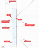
I spent some time today working up an approach for creating the quadratic throat design in Fusion360. The good news is that the process is fairly straightforward once I wrapped my brain around it. It also forced me to learn the surface tools in Fusion360, which I had not worked with before (I've mostly worked with the solid modeling toolset). This experiment resulted in a good design for a horn with the same angles as the SynTripP.
The bad news is that the process I used requires the horizontal and vertical horn planes to converge at the same distance from the mouth. In the SynTripP design (or at least my interpretation of it), the top and bottom horn planes converge about 1.1 inches behind the convergence of the left and right horn planes. I have not yet figured out an approach for drafting the required geometry for this scenario. Namely, I don't know how to handle the corners (which don't line up nicely if the planes don't converge at the same point).
Anyway, because this whole project is an exercise in developing my CAD/CAM skills, this has all been very interesting to explore. I'll keep plugging away at it.
Attachments
Last edited:
OK, a good night's rest and I feel like I've made a breakthrough.
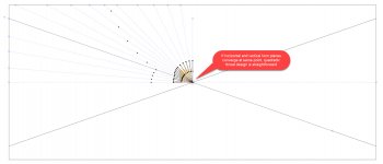
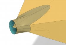
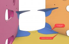
The key for me was understanding that the transition from the circular driver throat to the rectangular horn doesn't need to be confined within the throat adapter plate (TAP). Once I removed that constraint, a solution fell into place which I think is similar to the approach you took Art.
In this drawing, I allow the transition to continue to a depth of 1" inside the horn. This makes room for quadratic expansion on both the horizontal and vertical axes. It's not a "true" Quadratic-Throat Waveguide due to the fact that the SynTripP horn has multiple apices, but it follows the same principles and I'm pretty happy with the result.
Some filling and filing is indeed part of the finishing process. Alternatively, I could 3D print or mill the necessary inserts / cavities.
It will be a relief to wrap up the design side and get back to the fun part - fabrication!
Patrick
Attachments
Last edited:
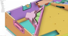
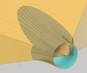
And here is a visualization of the "mudwork" area (in blue). I think there's actually enough meat/thickness in the mudwork that 3D printing the shapes and gluing them into place might work well. I'll try printing some tonight.
Attachments
Patrick,The key for me was understanding that the transition from the circular driver throat to the rectangular horn doesn't need to be confined within the throat adapter plate (TAP). Once I removed that constraint, a solution fell into place which I think is similar to the approach you took Art.
Looks like you are on the similar approach path now!
Art
I made a paper template then scanned it to jpg image with ruler tick marks. Then used image as reference for a spline curve. Then create body of revolution with spline. 20% fill is fine with 4 solid layers on surfaces. Drywall screws grab onto 20% infill PLA very well and PL premium adhesive bonds it to wood like no ones business.
Yours looks really good - don't forget to put round radius on edges where ports are to reduce turbulence noise and give room for Xdamage travel to prevent bumping cone into filler plug.
I have always wondered what the advantage is to making the cone shape...does it increase the compression ratio?
- Home
- Loudspeakers
- Multi-Way
- SynTripP: 2-way 2-part Virtual Single Point Source Horn