STLs
I don't think Mr Speakers has posted the STL's yet, unless I missed them?
They are actually in this thread a little way back there Mr. Waslo Bill Sir.
I don't think Mr Speakers has posted the STL's yet, unless I missed them?
On 7/16/19, in post #792 Mr Speakers wrote:I don't think Mr Speakers has posted the STL's yet, unless I missed them?
when we're finished we'll be happy to share STL files for print, cut sheets, and laser patterns. The project got slowed down due to a combination of parent-care and worked getting BUSY, but that's life for ya.
No STL files, cut sheets, or laser patterns have been posted here since then.
Art
No STL files, cut sheets, or laser patterns have been posted here since then.
Art
Thanks Art, I thought so.
Best,
JSS
Hi Adam, I was thinking along the same lines, and inquired about the TS parameters of this driver:Thanks Art!
If I want the loudspeaker to go lower than 82 hz, would that be possible with different 10 inch drivers? If yes, what parameters should I be looking for? The link you posted had some broken links, so I don’t know if I missed something important.
Gallien-Krueger 082-0460-C 10" Woofer For Neo 210, 410, MB210 | Full Compass Systems ..which, in it's cabinet dives to the low 30's in Hz..(I own one, and can attest to that..)
Alas, so far, they have not replied to my inquiry yet. Art's reply to your question, however, opens up a whole new can of worms, as he's correct that the whole design would have to be reworked... Don't know if it's worth the hassle...
DIY is so fun...lol...
I combed all 81 pages of this forum in hopes of digging up the most up to date plans for these speakers and have come up empty handed, for the plans that is. Managed to learn a lot to help me through to whole process of assembling a couple of these units. Can anyone help a guy out with the latest plans? I'm as committed and eager as they come. Anything is appreciated.
The directory at the bottom of the original post still points to the "latest plans",Can anyone help a guy out with the latest plans?
post #41 contains plans and a preliminary parts lists, post #61 has the completed parts lists and assembly instructions, post #100 has photos of the bass reflex port details, post #115 has the throat port detail. Posts #128,138, & 568 have injection port and cone filler details.
Art
Sorry I've been MIA, we're REALLY busy at the office right now and to get the STL and plans done we will put a BOM and other stuff together, otherwise we'll be creating work for anyone who tries plus ourselves. I hope we'll get this done this month...
Awesome!
After building a pair of Keystones, fine-tuning DSP to optimize them, and witnessing how great they perform, I've decided to put in the time and patience required to build a pair of SynTripPs to match with them...
I've got all cuts done and double-checked on most of their construction, minus the crucial bits and some detail work. I'll be using the handles Art suggests, and will be using a pre-manufactured Eminence pole mount (easy enough).
I'll also be using the Eminence N314T-8 which I don't think has been used/reported upon in the SynTripP. I'll measure and share results on that once I clear a few big hurdles... (I hope these aren't dumb questions, mostly, I hope their answers will help someone else who's struggling with them...)
1) Can dense 2" closed-cell foam (XPS) insulation be used as cone-filler material? (I think it's commonly referred to as rigid foam board)
2) Concerning part "E": In Art's parts list, it has a length of 15.125" x10.25" and the angle is listed as 43 degrees, but on Fin-Bot's plan layout, it's listed as 45.9 degrees, what gives?.
Is the 43 degrees calculated from part E's own surface, or from a surface that it will be mating? (for instance, the T.A.P. or part "M")
3) Fin-Bot's plans also call for a 45.9 degree angle on what appears to be part "M" ..and Art calls for 34.75 vertical.. (?!?)
4)Concerning Part "D": Again, the angles. Art's list calls for a 18.175 angle, but does not designate in the list, if that's the angle that mates with part "E" or part "N".
Fin-Bot's plans call for a 77.29 degree angle to mate with "E", and a 71.57 to mate with "N".
I realize some of these angles are listed 'flipped around' as in, which face of the board is being referenced, but even then, don't make sense to me...
BTW, Art clarified that all measurements near the rear of part "E" are symmetrical after someone posted the errors in FinBot's plan, I'm just repeating it here.
Understandably, some of these specs may seem 'self evident' due to some other corresponding spec listed elsewhere, (especially for folks who have built lots of cabinets), but the questions listed above, I've not found enough info to be able to deduce and come up with sure-fire answers.
So any, and preferably all, clarification would be a major help in clearing these initial hurdles. And thanks once again to Art for this great design!
Cheers,
-Steve
I've got all cuts done and double-checked on most of their construction, minus the crucial bits and some detail work. I'll be using the handles Art suggests, and will be using a pre-manufactured Eminence pole mount (easy enough).
I'll also be using the Eminence N314T-8 which I don't think has been used/reported upon in the SynTripP. I'll measure and share results on that once I clear a few big hurdles...
(I hope these aren't dumb questions, mostly, I hope their answers will help someone else who's struggling with them...)1) Can dense 2" closed-cell foam (XPS) insulation be used as cone-filler material? (I think it's commonly referred to as rigid foam board)
2) Concerning part "E": In Art's parts list, it has a length of 15.125" x10.25" and the angle is listed as 43 degrees, but on Fin-Bot's plan layout, it's listed as 45.9 degrees, what gives?.
Is the 43 degrees calculated from part E's own surface, or from a surface that it will be mating? (for instance, the T.A.P. or part "M")
3) Fin-Bot's plans also call for a 45.9 degree angle on what appears to be part "M" ..and Art calls for 34.75 vertical.. (?!?)
4)Concerning Part "D": Again, the angles. Art's list calls for a 18.175 angle, but does not designate in the list, if that's the angle that mates with part "E" or part "N".
Fin-Bot's plans call for a 77.29 degree angle to mate with "E", and a 71.57 to mate with "N".
I realize some of these angles are listed 'flipped around' as in, which face of the board is being referenced, but even then, don't make sense to me...
BTW, Art clarified that all measurements near the rear of part "E" are symmetrical after someone posted the errors in FinBot's plan, I'm just repeating it here.
Understandably, some of these specs may seem 'self evident' due to some other corresponding spec listed elsewhere, (especially for folks who have built lots of cabinets), but the questions listed above, I've not found enough info to be able to deduce and come up with sure-fire answers.
So any, and preferably all, clarification would be a major help in clearing these initial hurdles. And thanks once again to Art for this great design!
Cheers,
-Steve
Last edited:
Steve,1) Can dense 2" closed-cell foam (XPS) insulation be used as cone-filler material? (I think it's commonly referred to as rigid foam board)
2) Concerning part "E": In Art's parts list, it has a length of 15.125" x10.25" and the angle is listed as 43 degrees, but on Fin-Bot's plan layout, it's listed as 45.9 degrees, what gives?.
Is the 43 degrees calculated from part E's own surface, or from a surface that it will be mating? (for instance, the T.A.P. or part "M")
3) Fin-Bot's plans also call for a 45.9 degree angle on what appears to be part "M" ..and Art calls for 34.75 vertical.. (?!?)
4)Concerning Part "D": Again, the angles. Art's list calls for a 18.175 angle, but does not designate in the list, if that's the angle that mates with part "E" or part "N".
Fin-Bot's plans call for a 77.29 degree angle to mate with "E", and a 71.57 to mate with "N".
I realize some of these angles are listed 'flipped around' as in, which face of the board is being referenced, but even then, don't make sense to me...
1) My experience with that type of material is any type of machining it will cause it to flake apart. Even if you can get it into the correct shape, I'd be concerned that it bits will continue to shed, the interior is not designed to be exposed.
2) 2.9 degrees, from what you indicate..
3) Oh well..
4) Having sold the cabinets and disposed of my loft drawings, to answer your questions with more clarity would require duplication of what you will need to do to build the cabinets.
I'd suggest you loft (draw out) the plans full size, then you can measure all the angles and use scrap pieces of plywood to make sure they conform to the lay-out plan before making the final cuts.
Best of luck!
Art
Lost internet shortly after posting, but the answer to my 3rd inquiry came to me 2 hours after I posted, I had glossed over the 3rd dimension...... (turns out, fairly key)
I was also hoping to draw FinBot back out to explain why he did what he did, but alas, he hasn't, and his PMs have been full since I first tried to acquire the updated/final plans ...no doubt from ~200 other people trying the same thing...
(still wonder why he came up with what he did ..oh well...)
Lofting the build and using some scrap balsa for the cone fillers it is then...
I do appreciate the reply Art, it narrowed things down for me, which will help.
Cheers,
-Steve
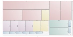
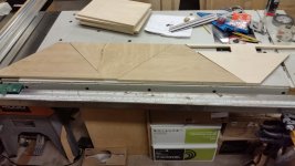
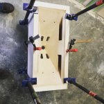
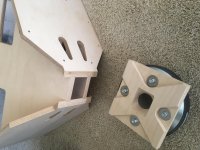
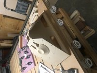
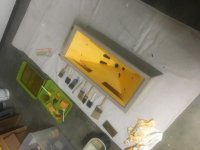
What I used for a preliminary cut-list, and how I wasted less wood fashioning Part 'D' ..(that's what the 12 x 64" cut is for...)
I've no idea if this'll help someone, but if it does, then good...
Have a great weekend everyone...")
I've no idea if this'll help someone, but if it does, then good...
Have a great weekend everyone...
Attachments
Thanks for the update
Great news, thanks for the update! Glad to hear you’re doing well.
Looking forward and thanks again!
Sorry I've been MIA, we're REALLY busy at the office right now and to get the STL and plans done we will put a BOM and other stuff together, otherwise we'll be creating work for anyone who tries plus ourselves. I hope we'll get this done this month...
Great news, thanks for the update! Glad to hear you’re doing well.
Looking forward and thanks again!
We wanted to post a few pictures of our SyntripPs and give a huge thank you to Art for putting these designs out there! Additionally, we have a few resources that might be a useful contribution to the community here, like a pretty professionally made SketchUp Model of the SyntripPs that should work well for anyone wanting to build their own set on a CNC router. This includes a model of the volume plug for the B&C 10CL51 woofer, and a model of the horn throats, which we also cut on a CNC. Before we post any plans i'd like to get one of the pros on here to sign off on them and make sure we have our dimension right (we may have taken a dimensional liberty or two). We are also using the B&C DE90TN 8ohm that Art sold us. I'll try to get some measurements out for the community here soon.
And thank you to everyone who has helped out on this thread, our non profit radio station KONR 106.1 Out North Radio and the dance music scene here in Alaska is eternally grateful!
Cameron and Kris,
And thank you to everyone who has helped out on this thread, our non profit radio station KONR 106.1 Out North Radio and the dance music scene here in Alaska is eternally grateful!
Cameron and Kris,
Build photos.
Build photos from Cameron and Kris's build.
We finished them out with an orange and gray stain, with an Osmo hard wax oil finish.
Build photos from Cameron and Kris's build.
We finished them out with an orange and gray stain, with an Osmo hard wax oil finish.
Attachments
Very clean look, nice work!Build photos from Cameron and Kris's build.
Build photos from Cameron and Kris's build.
We finished them out with an orange and gray stain, with an Osmo hard wax oil finish.
Very nice. Nice looking CNC there as well!
Two glamor shots,
This is my last post of glamor shots of the SyntripPs, it's all business after this. I wanted to show these things in actions.
The first is our non-profit radio station's (KONR 106.1 Out North radio) end of year party put on by the Beats Messiah crew. We took a boat to a remote cabin in Seward, AK and hauled the SyntripPs, an old Mackie 15" sub and a generator up a 250' + bluff overlooking Resurrection Bay...it really inspired us to make some handles on those things. The SyntripPs are ratchet strapped to the top some QSCs, which are pole mounted. Mixed with a 3-day cabin party it created the most precarious speaker setups i've ever seen.
The second picture is our radio station doing a DJ installation at the Anchorage Museum. We ran a series of free DJing workshops for students throughout the 2 week installation. We were running 1 Keystone at the time, should have 3 more finished in a few weeks!
- Home
- Loudspeakers
- Multi-Way
- SynTripP: 2-way 2-part Virtual Single Point Source Horn