Inspiration is from speaker dave's interview here:
[Interview] David Smith [English]
And his expanding line array design:
Snell Acoustics XA Reference Tower loudspeaker | Stereophile.com
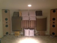
Attached is a pic of the speakers. I built some trial cabs just to try out the concept. The goal with this speaker design was to eliminate ceiling and floor reflections. It is supposed to be an expanding array with the array length increasing as the frequency is lowered. The outermost drivers have a LP at 125 Hz. The two central drivers have an LP at 500 Hz. And the KEF coax has an HP at 500 Hz. Then there is a passive crossover between the tweeter and the mid driver in the KEF Q100. There is some shelving of the mid and outer drivers to even the response.
Putting it in the corner gives it 90 degrees horizontal control to the low frequencies. I'm guessing that when you enter the wave region in the room, directivity is meaningless. Also, there should be no front wall reflection from the corner placement. Another big advantage.
There is a quadratic residue diffuser in the center and some thick absorbing panels. With this setup, the front wall completely disappears. There is a great sense of envelopment and a feeling of being in a different acoustical space.
My question is, are there any special rules to follow regarding the crossover and level? Is the approach to low-pass the outer drivers at progressively lower frequencies the correct approach? I've adjusted it to flat response and perceptually, it sounds flat.
Hoping that speaker dave chimes in, like he usually does. Any other thoughts, comments?
[Interview] David Smith [English]
And his expanding line array design:
Snell Acoustics XA Reference Tower loudspeaker | Stereophile.com
Attached is a pic of the speakers. I built some trial cabs just to try out the concept. The goal with this speaker design was to eliminate ceiling and floor reflections. It is supposed to be an expanding array with the array length increasing as the frequency is lowered. The outermost drivers have a LP at 125 Hz. The two central drivers have an LP at 500 Hz. And the KEF coax has an HP at 500 Hz. Then there is a passive crossover between the tweeter and the mid driver in the KEF Q100. There is some shelving of the mid and outer drivers to even the response.
Putting it in the corner gives it 90 degrees horizontal control to the low frequencies. I'm guessing that when you enter the wave region in the room, directivity is meaningless. Also, there should be no front wall reflection from the corner placement. Another big advantage.
There is a quadratic residue diffuser in the center and some thick absorbing panels. With this setup, the front wall completely disappears. There is a great sense of envelopment and a feeling of being in a different acoustical space.
My question is, are there any special rules to follow regarding the crossover and level? Is the approach to low-pass the outer drivers at progressively lower frequencies the correct approach? I've adjusted it to flat response and perceptually, it sounds flat.
Hoping that speaker dave chimes in, like he usually does. Any other thoughts, comments?
Attachments
cls, I figure that mid and tweeter's dispersion is wide enough. Corner placement minimizes early sidewall reflections, and therefore mid and tweeter should be placed deeply in the apex of the corner. With dsp it is possible to use time delay to each driver to get step response right
There has been a sideline discussion about similar construction here at diyaudio (synergy horn thread?) Sort of combination of Klipsch cornerhorn and synergy horn.
Using a line array bass helps to fight room modes and concentric mid-tweeter combo gives sharp imaging. This should be close to optimal configuration, when the room allows it (being symmetrical with straight clean walls)
Please ra7, tell us more, simulations, measurements, construction, everything!
My guess for sound tuning is to get a slightly recessing room response, measure one speaker at time, use rta ( and summing 20-30 cycles) or long gate 500ms. 40-200Hz straight, then gradually down 2dB at 100Hz and 3-5dB down at 5000Hz. I have found that I end to something like that if I tune by ear. The usual recommendation is straight up to 1000Hz, it leaves bass too lean for me!
http://www.prosoundweb.com/article/...ment_understanding_and_properly_using_rta_fft
Last edited:
I bet it sounds excellent.
The previous question is based on the concern of attenuation along radiating distance, in which the mid to high frequency would be attenuated more than the bass in this setup. Would it a problem?
And, as a fan of 3-front-channel, I'd suggest an additional (wide-dispersing) HF unit at the center in this already excellent system, to compensate the wide separated sources for pinna cue.")
The previous question is based on the concern of attenuation along radiating distance, in which the mid to high frequency would be attenuated more than the bass in this setup. Would it a problem?
And, as a fan of 3-front-channel, I'd suggest an additional (wide-dispersing) HF unit at the center in this already excellent system, to compensate the wide separated sources for pinna cue.
Please ra7, tell us more, simulations, measurements, construction, everything!
No simulations at all. Construction is pretty simple. Nothing spectacular as you can see. The boxes are built out of chip board. The main goal for me was to try the corner and expanding line array config. Intuitively, I knew it would work, so I thought I'd just give it a try. I took a chance with the placement of drivers. The outermost drivers are rolled off pretty early (125 Hz). I could've placed the outermost drivers anywhere on the baffle. Or there could be more drivers too.
The KEF cab and crossover design is documented here:
http://www.diyaudio.com/forums/multi-way/246147-diy-kef-q100-drivers.html
I really like the KEF Q100 unit. Super smooth response. The crossover and EQ is through a PC-based system that I recently built. It is documented here:
http://www.diyaudio.com/forums/pc-based/256809-setting-up-pc-based-multichannel-dsp-system.html
The PC-based system allows full freedom with crossover points, slopes, delay, phase correction. No hardware limits. At this point, the crossover points and slopes are somewhat arbitrary. I haven't spent a lot of time optimizing them. Slopes are LR48. Unfortunately, I'm on the road until Monday, so I won't be able to show measurements until Tuesday. Basically, I set it up flat at a distance of about 6-7 feet.
I bet it sounds excellent.
The previous question is based on the concern of attenuation along radiating distance, in which the mid to high frequency would be attenuated more than the bass in this setup. Would it a problem?
And, as a fan of 3-front-channel, I'd suggest an additional (wide-dispersing) HF unit at the center in this already excellent system, to compensate the wide separated sources for pinna cue.
This is a good question. I'm not sure what the answer is. Maybe speaker dave can enlighten us. Certainly, what I hear is not bass heavy. It does sound pretty good.
Last edited:
My question is, are there any special rules to follow regarding the crossover and level? Is the approach to low-pass the outer drivers at progressively lower frequencies the correct approach? I've adjusted it to flat response and perceptually, it sounds flat.
Hoping that speaker dave chimes in, like he usually does. Any other thoughts, comments?
I'm all for it!
Progressive low passes is the way to go if you have a line array of similar units, say a row of 4" full ranges. Then you would shoot for letting the effective array length stay in proportion to the wavelength.
Since you are using a variety of drivers sizes (therefore bandwidths) then you have to crossover high and low in the conventional way. For the XA series that is what I did. For the most part I empirically derived the designs using XOPT as the system simulation. I could track on axis, 15 degrees and 40 degrees up and down responses, and shoot for minimal change at 15 and lobe free constant drop at 40 degrees.
Geometry is key to this. You would love to have units spaced to less than a 1/2 wavelength apart at the tops of their respective bandpass (say, from M to M of the central MTM) but that is very difficult to achieve in practice. The greatest difficulty is getting a tight enough spacing between the tweeter and the 2nd-to-top elements. You have circumvented that by using a Uni-Q unit for the top crossover of 2 sections.
Based on that it would be nice to get a good match to the Uni-Q directivity for the lower sections. Your geometry is already fixed so the remaining variable is crossover points. If you don't have a simulator you can measure where your nulls and lobes come in by measuring up and down from the mid line and see if you can practically cross over before the worst off axis dips. Note that you can do some simple array modeling, good enough for your particular geometry, with Tolvin "The Edge".
I started with LR type crossovers but in the end had slightly better performance with non-symmetrical crossovers.
It will be interesting to see some measurements.
David
I bet it sounds excellent.
The previous question is based on the concern of attenuation along radiating distance, in which the mid to high frequency would be attenuated more than the bass in this setup. Would it a problem?
I think you are saying that the bass is more of a line array so it falls more slowly with distance.
If the XA (expanding array) is done right then it is a constant height with regard to wavelength, so it should drop with distance very uniformly.
In reality, when you get to the bass frequencies sound doesn't drop with distance at all since you are strongly into modal action of the room's standing waves. When standing waves occur then the pattern is balanced all over the room, meaning that peak level at a boundary is the same at the speaker end as at the far end.
I have worked with systems where different radiation patterns meant that varying drop with distance was a significant issue. The Mac XRT24 had a tweeter array and conventional woofer and mid. The line array falls off more slowly with distance. The only practical effect is that you should go out to your typical listening distance and do the response balancing there. Not a big deal.
David
Thanks Dave! I do plan to post measurements. Will do next week when I'm back home.
The 8" MM's are 21 inches apart (center to center). At 500 Hz, wavelength = 27 inches. So, they're a bit more than what is needed. A crossover at 330 Hz would put them 1/2 wavelength apart. That would eliminate the lobes or atleast make the central lobe very wide. The other option is to build a new cab for the KEF Q100. The cab right now is 11 inches tall. The driver itself is just 5 or six inches wide. I could also put the KEF cab on its side. That would result in a CTC of 18.5 inches.
The 8" MM's are 21 inches apart (center to center). At 500 Hz, wavelength = 27 inches. So, they're a bit more than what is needed. A crossover at 330 Hz would put them 1/2 wavelength apart. That would eliminate the lobes or atleast make the central lobe very wide. The other option is to build a new cab for the KEF Q100. The cab right now is 11 inches tall. The driver itself is just 5 or six inches wide. I could also put the KEF cab on its side. That would result in a CTC of 18.5 inches.
Dang, those newer KEFs aren't in the Goodwill store yet.
You can buy the Q100 bookshelves and then harvest the drivers. Or even use the same cab and upgrade the crossover. I think the bookshelf model uses a simple first order network.
Yeah I have a pair of early uni-q drivers with one impaired driver, so the internet search goes on for a working bass-mid. I'm inclined to like, prefer may I say, the co-axial approach, since we all have to choose something to prefer, right? We got to stand for something or we fall for whatever, no? Is that how that goes? FR drivers are coaxial, no?
Brief update: back from travel.
I tried some measurements yesterday. There is some phase warp due to latency in the measurement setup. With the convolution done through JRiver and the complex routing of output during measurements, there is a lag that is unaccounted for in Holm. The time lock feature in Holm doesn't seem to work properly. There is some discussion of this problem on the JRiver forum and I might ask a question there if I can't resolve it myself.
The phase warp could also be due to the high pass response of the sealed cabinet. I want to get a handle on what's going on before posting measurements. Stay tuned.
Measurement
Here's a measurement at 6ft from the corner on the axis along the midpoint of the KEF and Jamo drivers. The crossover is at 500 Hz, LR 48db/octave. Using rePhase for the convolution. I went ahead and flattened the phase as well. Looks pretty good doesn't it?
The second picture shows the individual driver responses. This is after convolving the raw driver response with the filter from rePhase.
I had done some measurement at different distances and different heights, but since then, I improved the crossover and haven't had a chance to repeat those measurements. Coming soon.
Attachments
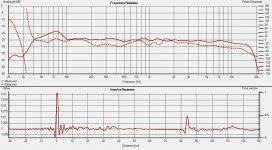
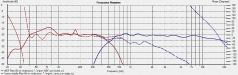
The latency problem is still there. I stopped using the JRiver convolution to do real time measurements. Now, the raw drivers are measured directly (EMU soundcard -> amp -> speakers), while capturing relative phase between drivers. Using this raw measurement, filters are generated in rePhase and imported into Holm for convolution. Finally, loopback through JRiver is used to confirm the result. So, the first graph in my earlier post shows the measured result with both drivers playing, the second graph shows the result of convolving the filters with the raw response.
Yes, there is a reflection at 80 cm. No, it isn't gated out. The response is 1/3rd octave smoothed. From my limited investigation, that reflection is from the sidewall. How would you get an idea of the low-frequency response if you gate out that reflection? With the corner loading and the effect of two woofers, a near-field measurement may not be very easily equalized for splicing with the far field response.
I've tried to lessen the smoothing and it tends to add more "grass" without doing much to the overall trend.
...Progressive low passes is the way to go if you have a line array of similar units, say a row of 4" full ranges. Then you would shoot for letting the effective array length stay in proportion to the wavelength...
David
Would you then be creating an extreme downward tilt with rising freq.? Where all the line is producing the lowest frequencies, with the associated high efficiency of all the drivers but, only the center few drivers are radiating higher frequencies with a much lower efficiency?
I would guess it is similar to a multi/symetrical .5 type system?
What I'm really wondering is if this could be used in an open baffle line array to counter the falling low frequency response?
No downward axis tilt since you would roll off drivers progressively around the middle driver. In other words both the top and bottom of the array would roll off in proportion to their distance from the center unit.
Yes, this would tend to elevate the low frequency response and could partially compensate for open baffle roll off.
David
- Status
- This old topic is closed. If you want to reopen this topic, contact a moderator using the "Report Post" button.
- Home
- Loudspeakers
- Multi-Way
- Corner Expanding Line Array with KEF Q100