You should learn to take criticism as intended - to help you, instead of being swift to take offence.Ok wont ask again i can sort it from the help ive bean given from system7
good bye an god bless")
Read again and you will realize I've given you the hints to successfully and cheaply repair your old 770s.
You should learn to take criticism as intended - to help you, instead of being swift to take offence.
Read again and you will realize I've given you the hints to successfully and cheaply repair your old 770s.
thanks
all ime trying to do is get the best out of my speakers and learn what i can.
as you can tell i came with little experience in speaker building or repair and figured i would ask people who do have knowledge and hoped i had come to the right place
.
i have lernet from this and hopefully will get things right now i have some advice on what things are in my xo i now know what a resister is and an inductor capacitor types and hopefully how to measure them and get the parts that will get the best from the speakers i have and hopefully improve what i can and get a little bit more from them
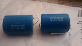
Do you find that the new polypropylene capacitors change the sound at all?
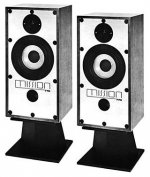
My first DIY project was a pair of DBS 4 loudspeakers, designed by David Berriman who was then a reviewer for Practical Hi-fi magazine. He designed more kits for magazines and then became a professional speaker designer later in his career. The DBS 4 was pretty much his take on a Mission 770- style design and used the SEAS H107 tweeter, later upgraded to a better SEAS tweeter, and eventually to a Morel MDT 30, which is essentially the same as the Morel tweeter you have.
My own experience was that the Morel was not as bright sounding as the SEAS tweeters, but that it was cleaner and basically just better. The 770s were a bit of a pivotal design and should sound good even by modern standards, particularly with the Morel tweeter.
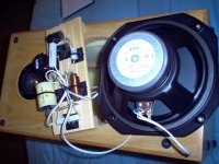
They do sound a lot better. Clearer and better defined with a better soundstage. It just seems to have got the drive units working together better. In the end I had to change them as one started to change and they no longer measured the same but they do seem to have kept their basic character.
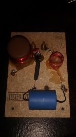
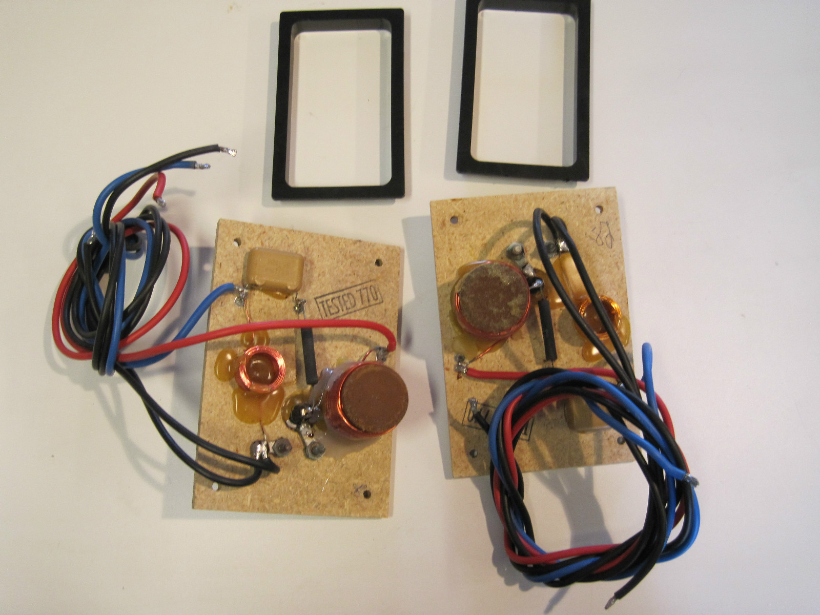
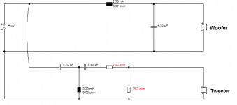
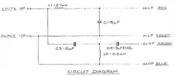
Original Crossover:
New 10uF polypropylene tweeter Crossover:

TBH, I can't imagine that original polyester was more than 3.3uF, but see how it goes.
The idea with SEAS 8" polypropylene bass drivers was they need little filtering. So a bass coil might do. 3kHz positive polarity crossover.
These days I do higher order filters. Along the lines of the classic KEF Celeste III. Maybe smaller bass coil, and bigger shunt cap maybe with some resistance added to avoid a peak at midrange caused by the bass units inductance. I don't like too much bass.
New 10uF polypropylene tweeter Crossover:
TBH, I can't imagine that original polyester was more than 3.3uF, but see how it goes.
The idea with SEAS 8" polypropylene bass drivers was they need little filtering. So a bass coil might do. 3kHz positive polarity crossover.
These days I do higher order filters. Along the lines of the classic KEF Celeste III. Maybe smaller bass coil, and bigger shunt cap maybe with some resistance added to avoid a peak at midrange caused by the bass units inductance. I don't like too much bass.
Attachments

Last edited:
Hi Steve,
You are supposed to add a zobel network across a woofer to correct for the rise in impedance due to inductance. That is always an R-C combination. There are ways to figure out the correct value.
Earlier you suggested the use of a cheap meter to read resistance. Why the heck would you try and use a meter that is inaccurate on it's least accurate function to read values you need to know accurately ??? Since you are measuring low resistances, you should be using a meter designed for low resistances, or a Kelvin connected measurement. Having the wrong answer is often worse than having no answer.
-Chris
A possible- even likely- improvement would be a complete redesign of the crossover to drop the handover between the drive units to 2kHz or so. The original SEAS tweeter wouldn't've coped with this, but the Morel will. This would give better directivity matching between the units and make more and better use of the tweeter. Should sound better, if done properly, but you would want to measure the drive units in situ to do that.
You really need a good multimeter to do any more than measure DC resistances. My one below does capacitance and inductance too. Very accurate.
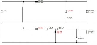
You then have a choice of circuit, but the SEAS 8" polypropylene units have a natural rolloff at 3kHz.
Along these lines. Resistances are a moveable feast, set by ear. Not hard. One of my BW3 modifications below. Probably the best circuit for this type of speaker.
You then have a choice of circuit, but the SEAS 8" polypropylene units have a natural rolloff at 3kHz.
Along these lines. Resistances are a moveable feast, set by ear. Not hard. One of my BW3 modifications below. Probably the best circuit for this type of speaker.
Attachments
-
 MonitorAudio R300-MD.jpg91.7 KB · Views: 378
 -
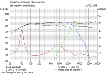 Vintage Speaker FR.PNG12.6 KB · Views: 199
 -
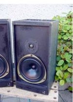
 Vintage Speaker 8 inch polycone dome tweeter.JPG24.8 KB · Views: 202
 -
 Vintage speaker second order.PNG6.2 KB · Views: 481
 -
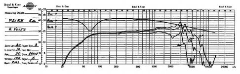 SEAS P21 RE 90dB 1.1mH Polycone.JPG66.4 KB · Views: 208
 -
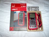 LCR Multimeter.jpg81.1 KB · Views: 486
thanks i have to get a good meter i had to send my caps to wilmslow audio so they could figure out what they were. i tried just changing the resisters and they didn't sound right at all so i put the original ones back in but iv bean rely busy looking after my mum so they had to take a back seat for a while but i recently notist an imbalance and when i measured them they measured differently so i dropped the cap's out and sent them in and got new ones. just glad i court it before it did any damage.
Even a cheap £10 multimeter can measure a 2.2R resistor or a 6R voicecoil resistance. What's hard about that?Hi Steve,
You are supposed to add a zobel network across a woofer to correct for the rise in impedance due to inductance. That is always an R-C combination. There are ways to figure out the correct value.
Earlier you suggested the use of a cheap meter to read resistance. Why the heck would you try and use a meter that is inaccurate on it's least accurate function to read values you need to know accurately ??? Since you are measuring low resistances, you should be using a meter designed for low resistances, or a Kelvin connected measurement. Having the wrong answer is often worse than having no answer.
-Chris
The business of added shunt resistance with a capacitor depends on the voicecoil inductance and the bass coil values. With KEF's 2.7mH and a bass unit below Le 0.9mH, you won't get a rise in the midrange. The classic 3:1 ratio of third order butterworth used in the KEF Celeste III.
With a smaller bass coil, you will need that shunt resistance. Lots of ways to do this. Troels even uses a 22R shunt on occasion, for only a slight rolloff:
CA18RLY/22TAF-G
It works.
Attachments
thanks i have to get a good meter i had to send my caps to wilmslow audio so they could figure out what they were. i tried just changing the resisters and they didn't sound right at all so i put the original ones back in but iv bean rely busy looking after my mum so they had to take a back seat for a while but i recently notist an imbalance and when i measured them they measured differently so i dropped the cap's out and sent them in and got new ones. just glad i court it before it did any damage.
I feel that 10uF on the tweeter is just plain wrong here.
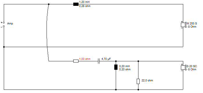
This is a 3kHz crossover with 8 ohm tweeter. You can use 3.3uF/0.3mH with little change. The bass coil is a matter of taste. Bigger makes for more bottom end. I usually place close to the wall, so I don't want big bafflestep boost. The red resistor is level adjust. Those Morels are quite efficient, for instance, so 6.2R might be appropriate. Select on test.
p21RE does not have inverted outer rubber as p21re-m has, that might differ slightly top end response
if i have time i´ll solder re-m out from 765 and give you guys some responses
I really don't think it matters. 3kHz rolloff is just what well-behaved 8" bass units do.
This is a 3.3uF/0.3mH tweeter filter. Probably 1.5mH bass coil. The only other variable is the series resistor in front of the tweeter filter. Depends on tweeter efficiency. Speakers are such an inexact science, I think you'd struggle to improve it without going higher order.
Hi slipmyster,
They were 10 uF at 63 V. Their measured value may have changed by now, and if they were electrolytic, their impedance is higher as the frequency increases. Replace with the same type of capacitor or your crossover will not work as the manufacturer intended.
Hi system7,
Your inductance / capacitance meter will be similar. Good meters such as the Fluke 87 series, or the new Keysight meters are much improved over what yours can do. That is why I bought and use an Agilent LCR meter + factory Kelvin leads (those cost more than your entire meter). The newer meters are improving, but you have to recognize their inaccuracies. Have you ever figured out the error budget for your multi-meter? Each function and range will be different, including where in that range you are measuring. It will be substantially worse than the basic DC accuracy stated on the box.
If you ever get a chance, compare your meter to a lab asset or calibrated instrument. An HP / Agilent / Keysight 34401A or better would be a suitable comparison product. They are a standard meter through much of the industry. A lab asset would be an HP / Agilent / Keysight 3458A (industry standard asset). If you have access to a Fluke 5500A or better calibrator, you can get a very accurate idea where the weak spots in your own meter will be. BTW, most cheaper multi-meters are inaccurate on their AC ranges once you reach 400 Hz. Really good hand held meters will extend their range to 100 KHz or better. They will also be true rms reading meters.
I am not trying to pick holes in your methods. All I am attempting to do is have you recognize the limitations of the equipment you are using, and what equipment you are recommending. If you are taking speaker design work on seriously, then you would be well advised to at least plan for equipment that will do the job you need, and at least buy a used example and have it calibrated. Then your work will more closely agree with the calculations.
Designing by ear isn't what I would call acceptable practice. The folks that did, did so early in their careers and have since obtained the equipment that is required. Designing loudspeaker systems today really does start with calculations and instrument readings. Listening to the end product does occur and is an important step. However, it is the math, measurements and listening tests that together create a good loudspeaker system. You don't need the last word in gear, but at least recognize the limitations with the equipment you have. Then either fix the situation, or accept that your methods are very approximate at best. When I started designing speaker systems in my late teens and through to my 30's, I did do my best to obtain what was really needed. I had my first HP LCR meter in my early 20's, and it was so useful that I maintained having an accurate LCR meter throughout my career. I even use it while putting the fine touches on the sound system electronics. It matters. Today I am using and Agilent 4263A. That's one you can buy used. I bought mine new to replace my damaged 4261A. There are much better instruments out there, but there are more that don't measure up.
Anyway, I hope this helps you recognize when and how some designs do not agree with the math behind the design. Look at what you are using and figure out your error budgets on the functions and ranges you tend to use. You only have to do this once for each piece of equipment. Also, critically important, keep your test leads in excellent condition, replace with good lead sets when they deteriorate, before they become intermittent. I'm trying to help you.
-Chris
They were 10 uF at 63 V. Their measured value may have changed by now, and if they were electrolytic, their impedance is higher as the frequency increases. Replace with the same type of capacitor or your crossover will not work as the manufacturer intended.
Hi system7,
Not true. The meter may indicate values of low resistance, but they are seldom accurate down there. The last two digits are likely completely irrelevant numbers. My experience comes from being a calibration technician working in an ISO calibration laboratory. Most cheap meters even fail their calibration from new, right out of the box with fresh batteries. Anyway, your advice is bad advice. At least tell people that the meter reading may be out by a good 10%. That is assuming they are zeroing their lead resistance out.Even a cheap £10 multimeter can measure a 2.2R resistor or a 6R voicecoil resistance. What's hard about that?
Your inductance / capacitance meter will be similar. Good meters such as the Fluke 87 series, or the new Keysight meters are much improved over what yours can do. That is why I bought and use an Agilent LCR meter + factory Kelvin leads (those cost more than your entire meter). The newer meters are improving, but you have to recognize their inaccuracies. Have you ever figured out the error budget for your multi-meter? Each function and range will be different, including where in that range you are measuring. It will be substantially worse than the basic DC accuracy stated on the box.
If you ever get a chance, compare your meter to a lab asset or calibrated instrument. An HP / Agilent / Keysight 34401A or better would be a suitable comparison product. They are a standard meter through much of the industry. A lab asset would be an HP / Agilent / Keysight 3458A (industry standard asset). If you have access to a Fluke 5500A or better calibrator, you can get a very accurate idea where the weak spots in your own meter will be. BTW, most cheaper multi-meters are inaccurate on their AC ranges once you reach 400 Hz. Really good hand held meters will extend their range to 100 KHz or better. They will also be true rms reading meters.
I am not trying to pick holes in your methods. All I am attempting to do is have you recognize the limitations of the equipment you are using, and what equipment you are recommending. If you are taking speaker design work on seriously, then you would be well advised to at least plan for equipment that will do the job you need, and at least buy a used example and have it calibrated. Then your work will more closely agree with the calculations.
Designing by ear isn't what I would call acceptable practice. The folks that did, did so early in their careers and have since obtained the equipment that is required. Designing loudspeaker systems today really does start with calculations and instrument readings. Listening to the end product does occur and is an important step. However, it is the math, measurements and listening tests that together create a good loudspeaker system. You don't need the last word in gear, but at least recognize the limitations with the equipment you have. Then either fix the situation, or accept that your methods are very approximate at best. When I started designing speaker systems in my late teens and through to my 30's, I did do my best to obtain what was really needed. I had my first HP LCR meter in my early 20's, and it was so useful that I maintained having an accurate LCR meter throughout my career. I even use it while putting the fine touches on the sound system electronics. It matters. Today I am using and Agilent 4263A. That's one you can buy used. I bought mine new to replace my damaged 4261A. There are much better instruments out there, but there are more that don't measure up.
Anyway, I hope this helps you recognize when and how some designs do not agree with the math behind the design. Look at what you are using and figure out your error budgets on the functions and ranges you tend to use. You only have to do this once for each piece of equipment. Also, critically important, keep your test leads in excellent condition, replace with good lead sets when they deteriorate, before they become intermittent. I'm trying to help you.
-Chris
Yeah and 765 has P21WN driverI really don't think it matters. 3kHz rolloff is just what well-behaved 8" bass units do.
Ye Gods, this Mission filter couldn't be simpler, could it?
Naturally I'd measure the DC resistance of the drivers and that one level-setting tweeter resistor. 10% accuracy would do. I could then guess the appropriate values. If it's a 10uF capacitor, we might be looking at a 4 ohm tweeter. IDK.
This is a bog-standard 3kHz simple filter. It plays nicely with 8" bass.
TBH, I have forgotten what we are trying to do here. Anybody remember?
- Status
- This old topic is closed. If you want to reopen this topic, contact a moderator using the "Report Post" button.
- Home
- Loudspeakers
- Multi-Way
- mission 770 crossover