I don't mean to burst anyone bubble but dipoles and cardioid woofers are free field systems. You don't get a dipole or cardioid pattern at a few feet from a wall. As was pointed out, by virtue of the differing distance to a wall form each source, each source of a dipole or cardioid will reflect off of all walls. When you are in a room all of these systems come down to multiples sources distributed around a room with each source having, perhaps, different magnitude and phase and delay. Specific arrangements and alignments will excite or fail to excite different modes but for analysis the modal response of each source can be considered separately and then the net result for all the sources is simply the superposition of the response of all sources. You can not discuss dipoles or cardioids without discussing source separation and orientation. Woofer systems which exhibit dipole or cardioid radiation in the free field will have certain behavior when placed in a room provided they are positioned with specific orientation. But in general they behave only as multiple sources.
You certainly won't burst my bubble but you should read my responses carefully.
Distance to the wall is not an issue. Only the apparent distance to the observer. Since we want to cancel a reflection across a boundary the actual distance is to the virtual image source, equivalent to the source distance plus 2× source to wall spacing. This should be more than far enough to be a far field condition.
I was doing some careful simulations a few weeks back regarding using a second driver on a wall surface to cancel the wall bounce from a system a few inches off the surface, say a typical hanging on-wall system. Interestingly, you had to consider the canceling driver as a 2 pi unit but the unit being cancelled is in 4 pi even though it is only inches off the surface. For complete boundary cancelation you adjust for equal contribution and opposite phase from your vantage point. (And it is easy to get complete cancellation.)
If you are not directly on axis to the source and reflection, then the proper delay can still give cancelation at your position, turning the cardioid into the appropriate hyper cardioid.
Yes, it is only one cancelation of one reflection, and many others exist, but if it is the earliest reflection this is a very good thing.
David
You certainly won't burst my bubble but you should read my responses carefully.
Distance to the wall is not an issue. Only the apparent distance to the observer. Since we want to cancel a reflection across a boundary the actual distance is to the virtual image source, equivalent to the source distance plus 2× source to wall spacing. This should be more than far enough to be a far field condition.
I was doing some careful simulations a few weeks back regarding using a second driver on a wall surface to cancel the wall bounce from a system a few inches off the surface, say a typical hanging on-wall system. Interestingly, you had to consider the canceling driver as a 2 pi unit but the unit being cancelled is in 4 pi even though it is only inches off the surface. For complete boundary cancelation you adjust for equal contribution and opposite phase from your vantage point. (And it is easy to get complete cancellation.)
If you are not directly on axis to the source and reflection, then the proper delay can still give cancelation at your position, turning the cardioid into the appropriate hyper cardioid.
Yes, it is only one cancelation of one reflection, and many others exist, but if it is the earliest reflection this is a very good thing.
David
There is a difference between making the contribution form a given mode null at a given point in a room and preventing that mode from being excited all together.
There is a difference between making the contribution form a given mode null at a given point in a room and preventing that mode from being excited all together.
Which is why I was careful to discuss the effects of a single boundary reflection, i.e. the nulling of the rear wall bounce.
With regard to standing waves, there are a number of papers out there that show significant reduction of standing waves in one direction through carefully aimed dipoles.
David S.
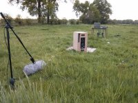
New measurements outdoor measurements today! Much better weather than last time, low winds and sunny 
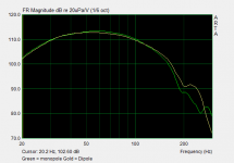
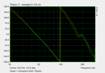
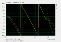
I concentrated on the (cardioid) sub again. I started off with a more easy option of equal response from monopole and dipole subs. And as a next step i added a high pass to the dipole and corrected the phase of the monopole using an allpass.
My method in steps:
1. Correct amplitude of monopole sub to linear from 40 - 150Hz, at 180 degrees
2. Correct amplitude of dipole sub to linear from 40 - 150Hz, at 180 degrees
3. Set optimum delay for dipole sub for equal phase (0.5ms)
4. Save DSP settings (full cardioid operation)
5. Set high pass @ 50Hz on dipole
6. Add 2nd order allpass filter (Q 0.70) to monopole @50Hz
7. Check for equal phase
8. Save DSP settings (monopole - dipool operation)
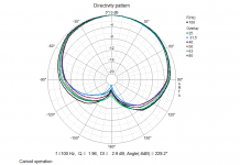
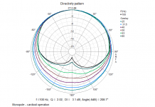
9. Reverse polarity of the dipole (resulting in cancellation @ 180 degrees). Polar patterns of both DSP presets.
The result was 15dB+ of suppression at the rear over the range of operation (30 - 150Hz) using the full cardioid preset. The polar pattern quite closely resembles a cardioid. Still, the prototype has some flaws: the (not so) sealed enclosure is too leaky causing 2 notches at the rear. And it's not symetrical, resulting in an "off axis" polar. However, this should suffice for some listening tests at home. Than i can also choose wheter i prefer monopole - cardioid operation or full cardioid for the sub.
I concentrated on the (cardioid) sub again. I started off with a more easy option of equal response from monopole and dipole subs. And as a next step i added a high pass to the dipole and corrected the phase of the monopole using an allpass.
My method in steps:
1. Correct amplitude of monopole sub to linear from 40 - 150Hz, at 180 degrees
2. Correct amplitude of dipole sub to linear from 40 - 150Hz, at 180 degrees
3. Set optimum delay for dipole sub for equal phase (0.5ms)
4. Save DSP settings (full cardioid operation)
5. Set high pass @ 50Hz on dipole
6. Add 2nd order allpass filter (Q 0.70) to monopole @50Hz
7. Check for equal phase
8. Save DSP settings (monopole - dipool operation)
9. Reverse polarity of the dipole (resulting in cancellation @ 180 degrees). Polar patterns of both DSP presets.
The result was 15dB+ of suppression at the rear over the range of operation (30 - 150Hz) using the full cardioid preset. The polar pattern quite closely resembles a cardioid. Still, the prototype has some flaws: the (not so) sealed enclosure is too leaky causing 2 notches at the rear. And it's not symetrical, resulting in an "off axis" polar
. However, this should suffice for some listening tests at home. Than i can also choose wheter i prefer monopole - cardioid operation or full cardioid for the sub.Attachments
Mad science at its best. I especially like the grassy ground plane.
That looks like a very good result. Similar to my experiments, you have to consider phase and amplitude in the rearward direction. Match them well and you will get good broadband cancellation, as you have.
I don't see the double dip you mention. Is this like a hypercardioid pattern? Note that if you want to cancel a rear wall bounce at an angle, rather than straight back, then hypercardioid may give greater cancellation.
I'm not sure which is better, or if the difference is significant, but it can be played with via the rear element electrical delay.
I hope you will end up with in-room measurement, because the potential cancelation of standing wave/improvement of the room curve is the objective.
Good stuff,
David
Haha, it felt a bit mad as wellMad science at its best. I especially like the grassy ground plane.
. The people hosting my measurement sessions on their field, found it fascinating as well .I was quite pleased with the result as well. We measured at 180 degrees, i could have possibly found a deeper null if measured slightly at a different angle. I ran out of time unfortunatelyThat looks like a very good result. Similar to my experiments, you have to consider phase and amplitude in the rearward direction. Match them well and you will get good broadband cancellation, as you have.
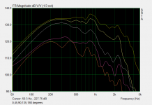
. The dips i referred to are not in the polar response but in the magnitude reponse at 180degrees. You are still slightly visible in the magnitude response of the monopole sub @ 196Hz and 255Hz. Before fastening the side panel, the dips were far more pronounced and somewhat lower in frequency.I don't see the double dip you mention. Is this like a hypercardioid pattern? Note that if you want to cancel a rear wall bounce at an angle, rather than straight back, then hypercardioid may give greater cancellation.
Does this work over a wide range?I'm not sure which is better, or if the difference is significant, but it can be played with via the rear element electrical delay.
Sure thing. Im going to finish the other prototype subwoofer (in 4 days actually). I'll do some more outdoor measurements of the woofer and compression driver and then ill move the set into my house and do indoor measurement of the indoor low frequency response.I hope you will end up with in-room measurement, because the potential cancelation of standing wave/improvement of the room curve is the objective.
Thank youGood stuff,
David
.That's better
Adding a delay should be effective over a wide range. I'd also expect a hypercardioid to be pretty effective at reducing irregularities in room.
Good job!
The way to think of it is to picture your speaker array in front of a large mirror. If you stand well in front of the actual speaker the array behind will be in line and the time delay between the monopole and dipole will be simply the time of flight of the physical distance between them.
Now if you walk to the side such that you are at a 30 degree angle relative to the speaker, you will also be about 30 degrees relative to the reflected monopole/dipole elements. This will contract their effective spacing so that you can still get full cancelation, but only if you adjust the time delay for the contracted spacing (cos30 = .866).
You should still get a broad (frequency) band null at the 30 degrees (from 180 straight back) and also 30 degrees on the other side, i.e. a hypercardioid pattern.
I spend some time thinking about your explanation but im afraid i still do not fully understand it yetThe way to think of it is to picture your speaker array in front of a large mirror. If you stand well in front of the actual speaker the array behind will be in line and the time delay between the monopole and dipole will be simply the time of flight of the physical distance between them.
Now if you walk to the side such that you are at a 30 degree angle relative to the speaker, you will also be about 30 degrees relative to the reflected monopole/dipole elements. This will contract their effective spacing so that you can still get full cancelation, but only if you adjust the time delay for the contracted spacing (cos30 = .866).
You should still get a broad (frequency) band null at the 30 degrees (from 180 straight back) and also 30 degrees on the other side, i.e. a hypercardioid pattern.
. The dipole and monopole are physically in line in my proto sub.My approach to a hypercardioid would be to increase the gain of the dipole elemenet, which would result in a small lobe at the rear and a null to the rear sides, the angle depending on the difference in gain. Or am i missing something
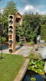
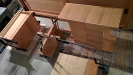
?Today i spent the whole optimizing the damping in the damped u frame of the woofer. Nasty business. Took me hours to get it as good as it was before. Dog didn't help . I actually used ground plane measurements rather than the speaker lifted 2m of the ground as the picture shows. At the end of the day i got one of the speakers right, but can't get the other one to match it . I tried to match the damping material as closely as possible, but still there were clear differences.
. I actually used ground plane measurements rather than the speaker lifted 2m of the ground as the picture shows. At the end of the day i got one of the speakers right, but can't get the other one to match it . I tried to match the damping material as closely as possible, but still there were clear differences.Attachments

Ok, time for some more measurements. I have spent some days with only the subwoofers in my home (two Hypex amps are rma, so i cant use top cabs yet). Reasonably pleased with them. Today i put them to the test.
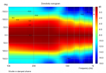
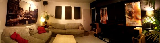
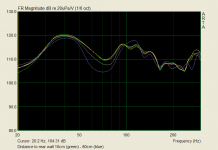
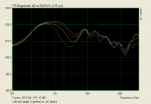
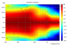
I made a comparison between different combinations of monopole and dipole, yielding different radiation patters. Subwoofers were positioned close to rear wall. Room is 6 x 4.2 meters, see attached picture (room is a bit longer than you can see here). Response was measured at listening position just before facing the opposite wall (3.5meters away), no gating and 1/6th octave smoothing. Results are quite close, no radiation pattern has the clear advantage to me. Cardioid seems to be able to pressurize the room as evidenced by rising respons towards 20Hz, as can be expected since it features a pressure source as well.
Not very pleased with the results, i tried measuring at multiple positions using both supercardioid and monopole radiation. I wile save you all off these images, but there was no clear winner here. Although the supercardioid seemed to be at a slight advantage showing slightly less variable freq response throughout the room (4 positions).
I suspected that the contribution of the dipole might be limited because of the proximity to the back wall. Although it shouldn't matter, since the netto contribution of the rear side should be 0 because opposing output of monopole and dipole woofers. The distance didn't change much, only with increasing distance a null appeared around 75Hz. Im not sure what this signifies.
Finally i tested the effect of a different angle for the dipole. Exciting the room modes in the perpendicular direction might yield a more even response. For both the right and left speaker, the respons got more even when more toe out or toe in was applied. The optimum was radiation to the sides for the dipoles for both speakers and this seems to work quite well for a single subwoofer. However, the summation of two subwoofers facing outward or inward is not optimal (but much better than both subs facing left or right).
It seems combining a single monopole and dipole combination can yield quite an even reponse, in my case by turning the dipole woofer 90degrees. However, im not sure what the best way of combining two of these subwoofers is. And whether this outperforms a multi mono sub setup, remains to be seen. It could well be mostly a waste of energy.
I made a comparison between different combinations of monopole and dipole, yielding different radiation patters. Subwoofers were positioned close to rear wall. Room is 6 x 4.2 meters, see attached picture (room is a bit longer than you can see here). Response was measured at listening position just before facing the opposite wall (3.5meters away), no gating and 1/6th octave smoothing. Results are quite close, no radiation pattern has the clear advantage to me. Cardioid seems to be able to pressurize the room as evidenced by rising respons towards 20Hz, as can be expected since it features a pressure source as well.
Not very pleased with the results, i tried measuring at multiple positions using both supercardioid and monopole radiation. I wile save you all off these images, but there was no clear winner here. Although the supercardioid seemed to be at a slight advantage showing slightly less variable freq response throughout the room (4 positions).
I suspected that the contribution of the dipole might be limited because of the proximity to the back wall. Although it shouldn't matter, since the netto contribution of the rear side should be 0 because opposing output of monopole and dipole woofers. The distance didn't change much, only with increasing distance a null appeared around 75Hz. Im not sure what this signifies.
Finally i tested the effect of a different angle for the dipole. Exciting the room modes in the perpendicular direction might yield a more even response. For both the right and left speaker, the respons got more even when more toe out or toe in was applied. The optimum was radiation to the sides for the dipoles for both speakers and this seems to work quite well for a single subwoofer. However, the summation of two subwoofers facing outward or inward is not optimal (but much better than both subs facing left or right).
It seems combining a single monopole and dipole combination can yield quite an even reponse, in my case by turning the dipole woofer 90degrees. However, im not sure what the best way of combining two of these subwoofers is. And whether this outperforms a multi mono sub setup, remains to be seen. It could well be mostly a waste of energy
.Attachments
Unfortunately no . I have zero experience with Cardioid designs.
I am closely monitoring few threads here to do some education. So THANKS a lot that you post your project. I have something in mind to build but that will need to wait until this FREEZING weather pass
Hope to compare notes by november... that's our SUMMER
. I have zero experience with Cardioid designs. I am closely monitoring few threads here to do some education. So THANKS a lot that you post your project. I have something in mind to build but that will need to wait until this FREEZING weather pass
Hope to compare notes by november... that's our SUMMER
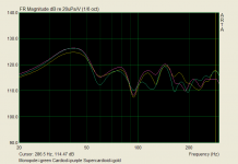
In the meanwhile i have built a new center speaker, also using a damped u frame to achieve a cardioid polar for midbass frequencies. The results is not perfect yet, presumably because the enclosure wasn't sealed properly by the baffle.
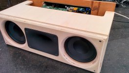
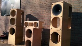
Currently im working on the front speakers plus extra sub. In total it wil be:
front speakers: 10"woofer + 10"waveguide
sub: multisub using 2 single10"sealed + 1 dual10"sealed + 1 15"sealed (4 subs total)
center: 2x6.5" + tractrix hf horn
Its a good thing i have an understanding girldfriend
Currently im working on the front speakers plus extra sub. In total it wil be:
front speakers: 10"woofer + 10"waveguide
sub: multisub using 2 single10"sealed + 1 dual10"sealed + 1 15"sealed (4 subs total)
center: 2x6.5" + tractrix hf horn
Its a good thing i have an understanding girldfriend
Attachments
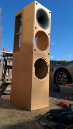
Some new progress, completed building the front speakers, sub and center. Next is working on the finish, applying absorption materials for cardiod polar and filter design.
Oh, and optimizing the multisub in my room, that we'll be a laborious process
Oh, and optimizing the multisub in my room, that we'll be a laborious process
Attachments
That's a lot of speaker . Love it.
Have you checked out Dutch&Dutch cardioid video on Facebook? Quite impressive
https://www.facebook.com/dutchanddutch
. Love it.Have you checked out Dutch&Dutch cardioid video on Facebook? Quite impressive
https://www.facebook.com/dutchanddutch
- Status
- This old topic is closed. If you want to reopen this topic, contact a moderator using the "Report Post" button.
- Home
- Loudspeakers
- Multi-Way
- Full range cardioid