Thank you and yes, funny that you mention them. They happen to be friends of mine and they brought me the idea of building a cardioid speaker 
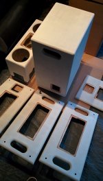
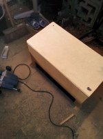
Applied the first layer of primer and one layer of woodstain.
Applied the first layer of primer and one layer of woodstain.
Attachments
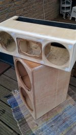
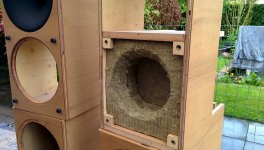
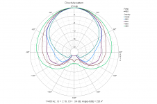
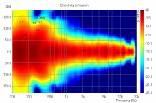
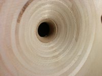
First measurements are in on cardioid behaviour of top cabinets. First tried without filling of the u frame behind the woofer, resulting in dipole radiation below the 1/4 wave resonance of the u frame en tending towards omnidirectional at the 1/4 wave resonance. Than added one layer of rockwool at a time. Optimal result was 4 layers of high density Rockwool of 50mm thick (so 20cm in total). Still some influence of the 1/4 wave resonance is visible but now polar is tending towards cardioid with 10dB+ LF cancellation at 180degrees. Results are quite similar to the prototype cabinets, now only with minor differences between the left and right (top) cabinet, which were probably related to leaky prototype enclosure. Im still going to try to add one more layer of rockwool to see if it further reduces the influence of the 1/4 and 1/2 wave resonance of the uframe.
Attachments
Here is a crazy idea.
Why not build a electronic bass trap for total cancelation of bass behind the speaker?
A monopole with a mic close to the cone as input. With the right polarity the cone should try to cancel all sound that reach the mic.
Not crazy and certainly doable, although a mic isn't needed. 2 elements with the right delay will create a cardioid. Jag is simply creating the same thing with acoustical delay through his cabinet.
Jag, very good results so far. Is the pattern maintained below 100Hz?
David
actually i use two psc 2.400s for 4 subs in total. So i run them stereo. Of course you could also sum the signal and feed them to both psc 2.400s, but probably it wont matter much in practice since bass is mostly monaureal anywayHello Jag768,
just a practical question,
when using the Hypex PSC 2.400 in the mono subwoofer and listening to stereo,
where do you get the stereo summing signal from, to feed into your subwoofer ?
Kind Regards
The garden i have used for measurements allow for a ~10ms gate, so i dont have reliable data for <100Hz. However, looking at the polar data is appears that the cardioid behaviour is lost <100Hz. The range <100Hz is covered by four subs placed throughout the room.Jag, very good results so far. Is the pattern maintained below 100Hz?
David
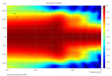
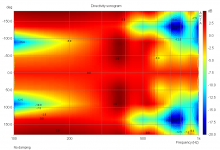
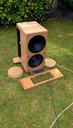
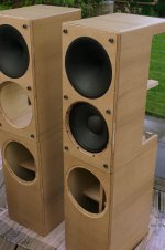
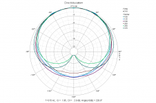
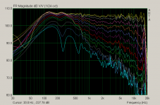
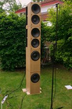
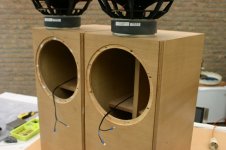
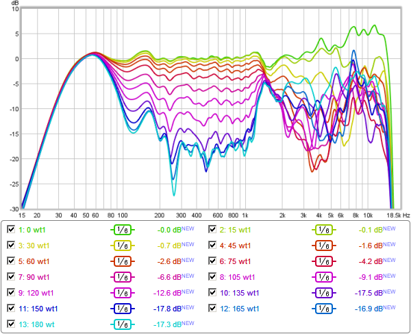
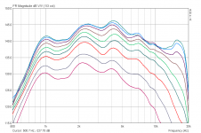
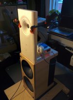
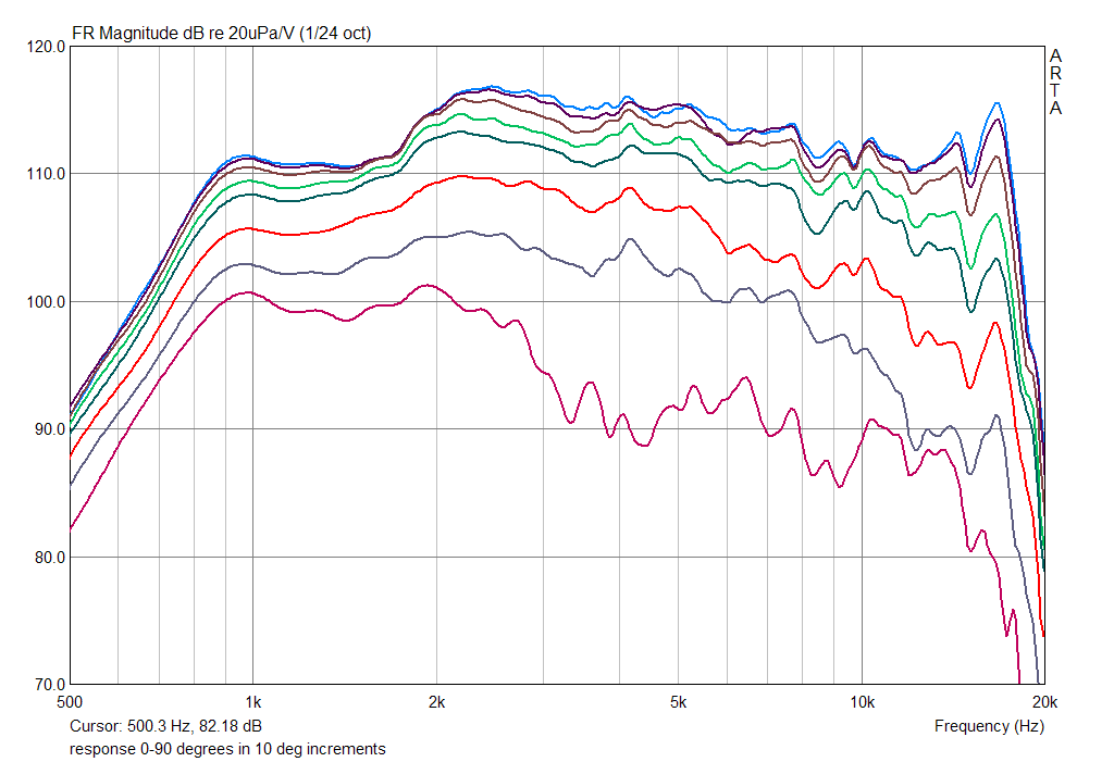
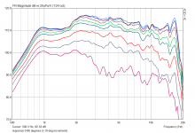
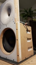
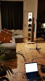
Some more pics are attached showing the final build, measurement setup, the filter simulation and on axis response. And horizontal directivity data shown in overlay in 10 degree steps, sonogram and polar.
Attachments
-
 Final polar - DI pattern mid.png42.8 KB · Views: 278
 -
 Final polar - DI pattern low.png45.1 KB · Views: 275
 -
 Filter ontwerp on axis response.png9.6 KB · Views: 299
 -
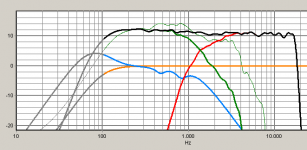 Filter simulatie.png20.9 KB · Views: 321
 -
 Directivity_overlays.png48 KB · Views: 382
 -
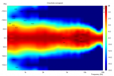
 Directivity_sonogram.png90.7 KB · Views: 514
 -
 Meten4.jpg236.1 KB · Views: 547
 -
 Final.jpg102.3 KB · Views: 487
 -
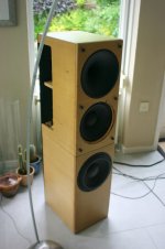
 Woofers2.jpg111.6 KB · Views: 402
 -
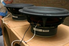 Woofers.jpg120.2 KB · Views: 446
Yes; a very impressive project.
Getting good amplitude matching is a key. Getting phase response of monopole and dipole elements and center to center distance to behave above dipole's natural peak is very difficult.
I've made a cardioid reference of limited SPL do to driver size; but demonstrate integration required to get 100Hz to about 1kHz:
Above are indoor measured at about 2 feet. Display is 110ms left and right windows with speaker about 5ft from walls and tweeter at listening height.
Your hand off to horn is excellent!
Some more pics are attached showing the final build, measurement setup, the filter simulation and on axis response. And horizontal directivity data shown in overlay in 10 degree steps, sonogram and polar.
Congrats, tour de force! Very similar to Kimmo's KS-1807, even the Hypex plate amp!
An externally hosted image should be here but it was not working when we last tested it.
Congrats, tour de force! Very similar to Kimmo's KS-1807, even the Hypex plate amp!
An externally hosted image should be here but it was not working when we last tested it.
Thank you. Looking quite similar indeed.
Most impressive especially what you achieve in the midrange!
Any further details about the construction (e.g. why you do not use side vents)? These seems much better.
Yes, side vents is something i would still like to try some day. I actually started with side vents, only situated more to the back. Couldnt get it to work. Bu my initial test enclosure was too difficult. In a later stage i added extra openings right after the baffle or halfway the u frame, neither worked very well. I might try to build a new test enclosure some day for testing side vents, a lot of people seem to have achieved good results with those!
So, time to move on and do a revision . A couple of things i'd like to improve:
- user friendliness: the Hypex amps (5 in total) need to be powered on individually because of start up current. I switched amps for my subs and i will do a passive filter for the tops.
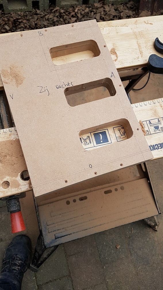
- midrange directivity: can be improved. Im going to try to use slots to reduce the midrange widening of the polar. I will test this on a test enclosure and then copy it to the "real" version.
- high frequency DI: it's a bit too narrow. Im thinking about ways to construct a waveguide which has a wider dispersion. I got a test baffle from a friend, and made an adaptor for a flat wavefront. Not perfect, but quite ok i would think.
Now i need to think of an economical way to make a new baffle and waveguide. Either wood/cnc, plaster or polyester. Im not sure which way to go.
. A couple of things i'd like to improve:- user friendliness: the Hypex amps (5 in total) need to be powered on individually because of start up current. I switched amps for my subs and i will do a passive filter for the tops.
- midrange directivity: can be improved. Im going to try to use slots to reduce the midrange widening of the polar. I will test this on a test enclosure and then copy it to the "real" version.
- high frequency DI: it's a bit too narrow. Im thinking about ways to construct a waveguide which has a wider dispersion. I got a test baffle from a friend, and made an adaptor for a flat wavefront. Not perfect, but quite ok i would think.
Now i need to think of an economical way to make a new baffle and waveguide. Either wood/cnc, plaster or polyester. Im not sure which way to go.
Attachments
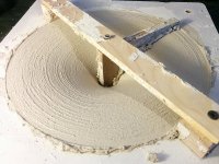
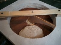
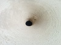
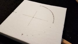
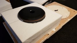
Today i made a test waveguide out of plaster.
I used an oblate spheriod profile (theta=50degrees) only using a large transition radius with the baffle of 6 inch. So the actual OS part is quite short. It's a 10inch waveguide with 2inch length.

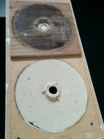
Using 3 layers of 12mm mdf board, i made a test baffle

Cut out the profile with a jig saw and mounted it in the middle which proved to be the hardest part. The B&C DE250 needs to be mounted from the inside, which also posed a challenge.

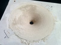
And in with the plaster which is really easy to work with


Now i have to patient and let it dry before doing the first measurements. I hope next weekend!
I used an oblate spheriod profile (theta=50degrees) only using a large transition radius with the baffle of 6 inch. So the actual OS part is quite short. It's a 10inch waveguide with 2inch length.
Using 3 layers of 12mm mdf board, i made a test baffle
Cut out the profile with a jig saw and mounted it in the middle which proved to be the hardest part. The B&C DE250 needs to be mounted from the inside, which also posed a challenge.
And in with the plaster
which is really easy to work withNow i have to patient and let it dry before doing the first measurements. I hope next weekend!
Attachments
How is your DutchIs this "plaster of Paris" or something else?
Thanks,
Jp
? Here's what i used. I think its indeed plaster of paris. But normally this is used for walls/ceilings. There's also yellow band and gold band, which have larger grain size (suitable for thicker layers).It works quite well when you cut off the threaded part of the throat. This worked out quite well for me. No diffraction visible in the polar! But mounting the compression driver to the throat is a bit complicated, i made an adapter out of mdf board which surrounds the throat of the waveguide.Sorry to stray off topic, but i was wondering on your impressions on the DE250 in the Dayton round guide?
So the response it quite flat using the Dayton (see screenshot couple of posts ago). Polar is good as well, only very narrow (60 to 40 degrees from 1KHz to 16KHz). So that's the reason i'm making a new one.
Constant vs narrow directivity has become quite the debate these days and I'm finding more and more people unhappy with in home sound of waveguides and returning to conventional devices on flat baffles. I find the round guides offer the best set of compromises with smooth response and less HOMs......but still narrow.
FWIW, my cardioid experiments mimic yours very closely but sadly didn't work once the prototypes were placed in the room as I simply didn't have the needed clearance around the bass units which resulted in some unwelcome resonance peaks as well as some deep notches. A Corner system is where I'll have to go next I believe OR small monitors and LOTS of room treatment! Lol
FWIW, my cardioid experiments mimic yours very closely but sadly didn't work once the prototypes were placed in the room as I simply didn't have the needed clearance around the bass units which resulted in some unwelcome resonance peaks as well as some deep notches. A Corner system is where I'll have to go next I believe OR small monitors and LOTS of room treatment! Lol
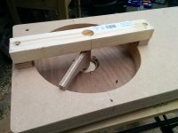
First results are in. The last part broke off when taking off the back unfortunately (not unexpected though).

Its still looking rough


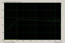
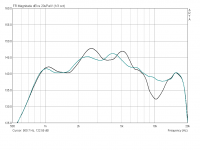
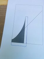
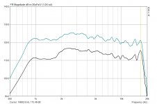
Amplitude response has improved considerably compared to the previous test baffle/waveguide i used. It's quite close to the Dayton waveguide on axis response (shown in green).

Only now the polar / dispersion is much wider, about 100degrees

Rounding off the baffle sides might improve some diffraction in the midrange. And im going to try improving the throat.
Its still looking rough
Amplitude response has improved considerably compared to the previous test baffle/waveguide i used. It's quite close to the Dayton waveguide on axis response (shown in green).
Only now the polar / dispersion is much wider, about 100degrees
Rounding off the baffle sides might improve some diffraction in the midrange. And im going to try improving the throat.
Attachments
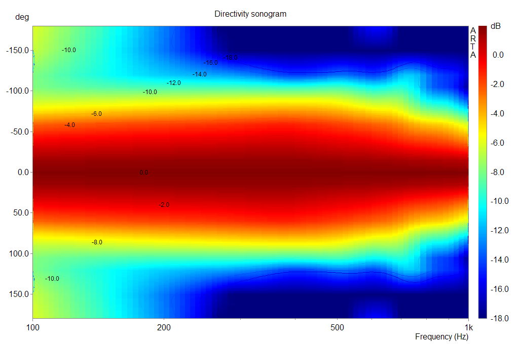
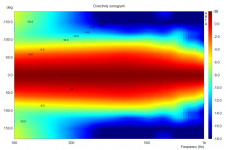
New measurements are in of the prototype enclosure for the revision of my cardioid enclosures.


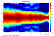
Full space measurements. Gate was set to 6.2ms. the wheater did not permit outdoor measurements.

Resulting directivity sonogram quite closely resembles a cardiod in the range of interest (150 - 500Hz).
Full space measurements. Gate was set to 6.2ms. the wheater did not permit outdoor measurements
.Resulting directivity sonogram quite closely resembles a cardiod in the range of interest (150 - 500Hz).
Attachments
There are no formulas that i know ofHey Jag768, nice project! The plaster waveguides and your new cardiod results look great.
What woofer are you currently using?
What material are you using inside the box?
What formulas did you use to calculate the position and dimensions of the side vents?
Cheers, Mark
. 'The material that is used for the inside is Akortherm. The woofer is the AD R1030, from some less known chinese manufacturer.- Status
- This old topic is closed. If you want to reopen this topic, contact a moderator using the "Report Post" button.
- Home
- Loudspeakers
- Multi-Way
- Full range cardioid