After reviewing the entire Pass thread, I can't see any reason why I should expect a resonance anywhere below 250hz, and if I'm carefull with choosing the slope the resonant peak might be an advantage given the typical in room null found in that area.
You are right, it's pretty much the speed of sound divided by 4 times the depth of the slot or about 250Hz, but I prefer to stay at least an octave away from resonance to avoid any "hangover" in the response.
I like the sound. The aren't for everyone, but they do interact differently
with the room than a closed box speaker.
You might take a look at the OB I showed at the last Burning Amp Festival,
which is different.
Here is the woofer response curve at 1, 2 and 3 meters taken outside and
driven by a B5 crossover/eq The red is the front response, the blue is
with the speaker turned around and the top curves are 1 meter.
Attachments
Thanks for the feedback and graphs. I think I'm gonna give it a go with 4 10" woofers. I'll have to get a different amp for the bottom......probobly a Pro amp with DSP or maybe a DSP unit before the bass amp...we'll see.
What's your feelings on high Qt drivers in this application?.........think it's neccessary?
What's your feelings on high Qt drivers in this application?.........think it's neccessary?
I like the sound. The aren't for everyone, but they do interact differently
with the room than a closed box speaker...
Nelson, Thanks for weighing in!

Your earlier slot loaded design was an inspiration for the compact system documented here.
Woofer Q: Low or High?
The prevailing design concept proposed by M. J. King was to use high Qts drivers to allow construction of a purely passive system that required no eq.
I have heard Alpha 15A (high Q) designs and also several of my own with more moderate Q (~0.5) drivers and my feeling is that the lower Qts systems sound tighter. This makes perfect sense, the electrical system has better coupling with the cone for more control. The lower you go in Q the higher they start to roll-off, so you need more eq. and more power. You'll probably have a really good starting sensitivity with the four 10's so it'll be easily manageable.
John K's ABC dipole is an excellent simulation tool to get an idea of the response to expect A, B, C, Dipole. You can simulate the system as a flat baffle an H-frame and a U-frame
I have also used Basta Tolvan Data which has a Maximum Output Level (MOL) curve you can enable to can see how much output you can get at a given frequency with a certain number of watts (volts) and X-max. I simulated my slot design as a flat baffle (made it 2x wide as the rear box was deep to get an idea). It predicts pretty well on axis and at small angles (but not well at wide angles). Basta is the more full featured version of the Edge freeware, for 25 euro it allows simulation of multi-way designs and has more features. It's really easy to use for quick design checks, much easier than SoundEasy, which is my other go-to tool.
Still would want to cross them lower than you have in mind, but if you have a DSP x-over it's easy to make changes quick and listen to the result.
Z
What's your feelings on high Qt drivers in this application?.........think it's neccessary?
The prevailing design concept proposed by M. J. King was to use high Qts drivers to allow construction of a purely passive system that required no eq.
I have heard Alpha 15A (high Q) designs and also several of my own with more moderate Q (~0.5) drivers and my feeling is that the lower Qts systems sound tighter. This makes perfect sense, the electrical system has better coupling with the cone for more control. The lower you go in Q the higher they start to roll-off, so you need more eq. and more power. You'll probably have a really good starting sensitivity with the four 10's so it'll be easily manageable.
John K's ABC dipole is an excellent simulation tool to get an idea of the response to expect A, B, C, Dipole. You can simulate the system as a flat baffle an H-frame and a U-frame
I have also used Basta Tolvan Data which has a Maximum Output Level (MOL) curve you can enable to can see how much output you can get at a given frequency with a certain number of watts (volts) and X-max. I simulated my slot design as a flat baffle (made it 2x wide as the rear box was deep to get an idea). It predicts pretty well on axis and at small angles (but not well at wide angles). Basta is the more full featured version of the Edge freeware, for 25 euro it allows simulation of multi-way designs and has more features. It's really easy to use for quick design checks, much easier than SoundEasy, which is my other go-to tool.
Still would want to cross them lower than you have in mind, but if you have a DSP x-over it's easy to make changes quick and listen to the result.
Z
The slot loaded OB is fairly straight forward to sim in AkAbak and I found that it was very helpful in seeing the differences in low vs high Q drivers as to where the bass roll off was and how much xmax was left to EQ. It is not as simple as saying a low Qts driver can be EQ'd back as you need to make sure there is still stroke left for sufficient SPL. Having lots of drivers always helps. The simulation also lets you see where the upper max frequency is before a huge slot loaded peak occurs so that you can try to XO before that point. Although with DSP that can be EQ'd flat too.
With 4 stacked 10" drivers, you'll get the vertical dispersion characteristic of a 40" diameter driver, which should help with ceiling bounce.
I've been modelling slot loaded woofers in hornresp as offset conical horns, which I can do because I'm using a slot profile from the side that is triangular, point towards the back, flat towards the front. This gives quite wide BW depending on the depth of the slot and how much offset. You have flexibility there if you make throat area less than Sd of the driver....
I've been modelling slot loaded woofers in hornresp as offset conical horns, which I can do because I'm using a slot profile from the side that is triangular, point towards the back, flat towards the front. This gives quite wide BW depending on the depth of the slot and how much offset. You have flexibility there if you make throat area less than Sd of the driver....
The simulation also lets you see where the upper max frequency is before a huge slot loaded peak occurs so that you can try to XO before that point. Although with DSP that can be EQ'd flat too.
The example above was with a 15" Eminence Definimax (my current favorite)
and you can clearly see the peak at around 200 Hz. You definitely want to
be out of there at a frequency lower than that. I cross that system on the
low end at 80 Hz or so at 12 dB/oct, and it meets the Lowther 8" drivers
nicely at about 160 Hz (in phase).
Nelson's latest OB?
Nelson,
I looked for your latest OB design and only found one photo from a rear high 3/4 angle in a magazine write-up. Do you have a link to more information or a couple of photos you can post?
Z
...You might take a look at the OB I showed at the last Burning Amp Festival...
Nelson,
I looked for your latest OB design and only found one photo from a rear high 3/4 angle in a magazine write-up. Do you have a link to more information or a couple of photos you can post?
Z
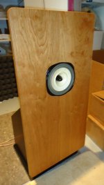
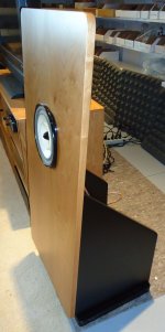
Sorry, here you go.
Nice work, looks like you really upgraded your woodworking!
What was the thought re the horizontal slot at floor level? Was this just to allow a lower profile overall or is there some significant acoustical effect from radiating into pure 1/2 space?
How is this on vibration from the woofer since there is no force canceling?
So many questions???
Mr Pass,
This is a very simple and clever design to add floor loading to the woofer: +3dB on the bass for free - bingo! I think the substantial 3/4in thick box and slot and fact it is floor mounted probably really reduce any vibration issues. Your 6 driver slot loaded OB was the inspiration for my cardboard OB ( http://www.diyaudio.com/forums/full-range/249984-cheap-fast-ob-literally.html ) - which works terribly well for using only $40 (6x$5+$10) worth of drivers.
This is a very simple and clever design to add floor loading to the woofer: +3dB on the bass for free - bingo! I think the substantial 3/4in thick box and slot and fact it is floor mounted probably really reduce any vibration issues. Your 6 driver slot loaded OB was the inspiration for my cardboard OB ( http://www.diyaudio.com/forums/full-range/249984-cheap-fast-ob-literally.html ) - which works terribly well for using only $40 (6x$5+$10) worth of drivers.
That's a fantastic project.Been building open baffle dipole loudspeakers since 2009. Inspired by Linkwitz, Martin J King and John Kreskovsky, an idea always starts as "I could just make holes in a board and... poof- I would have a OB panel that would look like an electrostatic once a grill was on." Each time the reality was much harder: after a support structure and a box for the bass radiators was designed, it morphed into a much more ambitious project. Then, after countless weekends of woodworking & finishing, each project would end with tendonitis in my elbows and MDF dust in my sinus tract and eyes. (Never had any energy left to finish a grill on any project.) Each time my friends were amazed with the open sound, but the measurements were not as good as I wanted (I keep getting more picky about the directivity). Rinse and repeat.
View attachment 404713
Woofer Directivity
The various iterations left me with know how concerning cut-outs in the baffle to shape the directivity, constrained layer damping (CLD) to lower baffle vibration and shaping the rear of a U-frame to minimize resonance. My wife was pressing for something smaller (and with less wires!) With my elbows recovered last Spring I tried again. At one point, I had purchased about 80 Aura/ NS6-255-8A woofers for $6 each after finding them to have a surprisingly linear motor. Using these in the slot-loaded OB woofer concept that Nelson Pass had documented in conjunction with a small U-frame, a reasonably small OB concept emerged. The force-canceling of the slot set-up would minimize vibration from the woofers which was always unsettling in previous designs.
I decided to get all of the parts CNC cut; finishing would be limited to just a spray coat of clear shellac. Then it would be just assembly and wiring- able to be done in just a couple of weekends. The grill would be integrated into the design with fabric stretched over the baffle. Instead of a stack of external amps and a DSP crossover, I would spring for Hypex AS2.100d modules (a DSP crossover and bi-amp plate amp) and integrate them into the speakers.
View attachment 404715
Exploded View
The results were so good, especially with respect to lowering the effort, I thought that others would be interested in how these went together. So here's how it went-
The idea was to get all of the parts for one speaker cut from a single sheet of 1/2 inch MDF. This allows the CNC to cut all from one side in one pass (no need to turn over the pieces and register them for cuts on the backside), so the cutting cost is low. The front baffle is a lamination of two of the 1/2 inch parts sandwiched over a viscoelastic layer to form a 1.06" (27mm) thick baffle. The woofer slot assembly is glued into the baffle. The rear U-frame box bolts on to the baffle/slot assembly and holds the Hypex modules. (See exploded view.)
View attachment 404706
All from one sheet of MDF
An ME I work with helped me develop the SolidWorks 3D model one Saturday afternoon from sketches. Construction was indeed completed in a couple of weekends, measurement and tuning of the Hypex crossovers was perfected over a few more days. They looked so good in just clear shellac that I still have yet to install the grill fabric- LOL.
The midrange section is a 1-1/2 way setup using two 3-1/2" Vifa/TC9-FD-18-04 (with a 1.3mH inductor in series with the top one). The tweeter is a Vifa/OX20SC00-04 in a waveguide robbed from a Nuance/TW5-073LR; this combination has very constant directivity above 4kHz but the Vifa mids sounded so good equalized to 20kHz, that I never put in the effort to build the crossover for the tweeter- so right now it's "justfa show". The slot loaded woofer is made using eight NS6-255-8As for a total radiating area (Sd) of 1088sq-cm, about the same area as a 20" woofer!
View attachment 404712
On Axis Response
The overall results were impressive, especially considering the total cost was under $1,000 for a pair, complete with electronics. The Hypex modules are a bit pricy, but they have analog, SPDIF & USB inputs and dedicated (stereo or mono) subwoofer outputs (if you really NEED that last bottom octave). And you can switch inputs and control volume with an IR remote. The system is a complete stereo without the rack. My son uses his iPod as a source, I listen using my laptop as the source.
View attachment 404714
MF-HF Directivity
I will let the data speak for itself, but everyone who has heard them has been impressed with the rock solid imaging and tonal balance. I was slightly disappointed with a "shoulder" in the directivity plot around 1.3kHz, but overall it's very good. Response is +/-2dB from 35-20kHz on axis except for a 3.5dB dip around 1.3kHz that's on purpose. The true standout though, is the bass; the directivity is an almost perfect dipole as the outdoor measurements below show (un-gated, 2m ground bounce). A double bass, cello or a kick drum sounds like it's in the room, really. The speakers don't get at all muddy if you want to listen to Slipknot (which I don't). Toms hit you in the chest. You can feel no bass vibration in the baffle, the woofer force-canceling really works. Mid frequency vibration in the baffle is very low, the damping layer works.
View attachment 404710
Baffle before shellac & drivers.
Notice black line on the edge- it's the damping layer.
What do you think it is?
As for the construction- I am never going to cut another board again unless it's for a test baffle. Everything fit perfect and tooling holes made the alignment of the parts during gluing a breeze. The damping layer was a bit of a challenge to trim, but still easy in the light of past projects.
View attachment 404717
Done in two weekends- ready to tune.
Looking forward to comments. I have more data/pictures.
Feeling very humbled about my own efforts!
Do the cut outs around your mid/ high frequency drivers help with imaging?
Or is this to assist dipole cancellations, or both?
Do the cut outs around your mid/ high frequency drivers help with imaging?
Or is this to assist dipole cancellations, or both?
Appreciate the compliments, as you have read, it was more about avoiding effort and annoyance that it was about craftsmanship- but the end result was good.
With respect to the cut-outs, I have been trying different cut-outs in baffles since I started in 2009. Sometimes with good results, sometimes just OK. The idea is to have uniform (dipole) cancellation with frequency which increases the direct amplitude relative to the reflected power- this increases imaging (given good source material). The reflection from the wall behind the speaker is strong-ish, but it's delayed enough to be perceived as ambiance and not a smeared image. Having the baffle cut out underneath the mid range specifically helps reduce ground bounce.
In this example you can see from the data, that the directivity vs frequency is pretty good, much better than a typical two-way. Some test baffles have done better, but for this effort I just guessed on the cut-outs, in keeping with my low-effort mantra for this pair.
We are also discussing cut-outs in this thread: http://www.diyaudio.com/forums/full-range/249984-cheap-fast-ob-literally-20.html
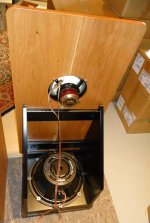
Poor man's turntable
A couple of people have asked me about the turntable used to perform horizontal polar measurements. Below are details of the turntable I whipped up. This saved me a lot of time. What I used to do before was move the speaker around on a piece of paper with angles marked on it. But that was problematic, time consuming and especially difficult when I used a raised platform like a stool or stand to hold the speaker.
I wanted something low profile so it would not disturb ground plane measurements, when I made them. Doesn't get much lower profile than this:
.jpg")
The Completed Manual Turntable
The design is nothing special, but it was very fast to make and used only a 24" x 36" piece of 1/2 inch birch plywood and a 14" x 17" platform of 3/4 inch MDF and a single 5/16" bolt+nut. It's very effective and easy to transport to outdoor sites.
 (2).jpg")
Easy to Set the Angle
This is how you make one:
1. Cut the plywood rectangle and the MDF rectangle. (You can get this done at a home center like Home Depot if you don't have a table saw.)
2. Draw and print a protractor pattern on a an ANSI E size sheet (34" x 44") with a medium format printer. (You can get this printed at your local Kinko's, etc. if you don't have access to a plotter.) The pattern I used was designed to work from 0-180 degrees (black numbers) or +90 to -90 degrees (red numbers).
3. Use the print to mark the hole in each piece. Pilot drill, counter bore to the diameter of the washers so the hardware will be flush or below the surface, then drill the hole for the bolt.
.jpg")
Hardware Below the Surface
4. Draw a line in the center of the MDF rectangle as shown in the photo.
5. Adhere the printed sheet to the plywood with light duty spray adhesive.
6. Install the stainless steel 5/16" bolt as a pivot, with washers and a nylon-insert lock-nut.
7. Apply a coat of paste wax on the back of the platform (the side that slides against the printed sheet) this leaves it with just the right amount of friction. It moves easily under load, but won't overshoot past the mark.
-Finished.
Even though the platform is only 14" wide I have used it with speakers up to 20" wide and it works well with a stool or a speaker stand. The pivot is not forever, but for the hobbyist, it should last for years.
I have to look for it, but I will post a PDF of the pattern in a couple of days. (And the original Visio drawing, if anyone asks.)
Z
A couple of people have asked me about the turntable used to perform horizontal polar measurements. Below are details of the turntable I whipped up. This saved me a lot of time. What I used to do before was move the speaker around on a piece of paper with angles marked on it. But that was problematic, time consuming and especially difficult when I used a raised platform like a stool or stand to hold the speaker.
I wanted something low profile so it would not disturb ground plane measurements, when I made them. Doesn't get much lower profile than this:
The Completed Manual Turntable
The design is nothing special, but it was very fast to make and used only a 24" x 36" piece of 1/2 inch birch plywood and a 14" x 17" platform of 3/4 inch MDF and a single 5/16" bolt+nut. It's very effective and easy to transport to outdoor sites.
Easy to Set the Angle
This is how you make one:
1. Cut the plywood rectangle and the MDF rectangle. (You can get this done at a home center like Home Depot if you don't have a table saw.)
2. Draw and print a protractor pattern on a an ANSI E size sheet (34" x 44") with a medium format printer. (You can get this printed at your local Kinko's, etc. if you don't have access to a plotter.) The pattern I used was designed to work from 0-180 degrees (black numbers) or +90 to -90 degrees (red numbers).
3. Use the print to mark the hole in each piece. Pilot drill, counter bore to the diameter of the washers so the hardware will be flush or below the surface, then drill the hole for the bolt.
Hardware Below the Surface
4. Draw a line in the center of the MDF rectangle as shown in the photo.
5. Adhere the printed sheet to the plywood with light duty spray adhesive.
6. Install the stainless steel 5/16" bolt as a pivot, with washers and a nylon-insert lock-nut.
7. Apply a coat of paste wax on the back of the platform (the side that slides against the printed sheet) this leaves it with just the right amount of friction. It moves easily under load, but won't overshoot past the mark.
-Finished.
Even though the platform is only 14" wide I have used it with speakers up to 20" wide and it works well with a stool or a speaker stand. The pivot is not forever, but for the hobbyist, it should last for years.
I have to look for it, but I will post a PDF of the pattern in a couple of days. (And the original Visio drawing, if anyone asks.)
Z
- Status
- This old topic is closed. If you want to reopen this topic, contact a moderator using the "Report Post" button.
- Home
- Loudspeakers
- Multi-Way
- Novel Open Baffle Construction Techniques