I've been experiencing a bit of a 'gut check' with this project.
Basically, I have two horns running, and it sounds *excellent*. In fact, this may be one of the best car stereo 'front stages' that I've ever heard.
BUT...
The distortion is an issue. As detailed in the last couple pages, I think the distortion is mostly due to three things:
1) high excursion in the dipole midranges
2) vibration in the horn itself; I didn't realize that these mids would generate so much force!
3) I didn't realize that the shape of the midrange ports had such a huge impact on distortion. So I have a catch-22; use big ports for low distortion and muck up the compression driver. Or vice versa.
I'm definitely not throwing in the towel just yet, but I *am* going to explore alternatives for a few days.
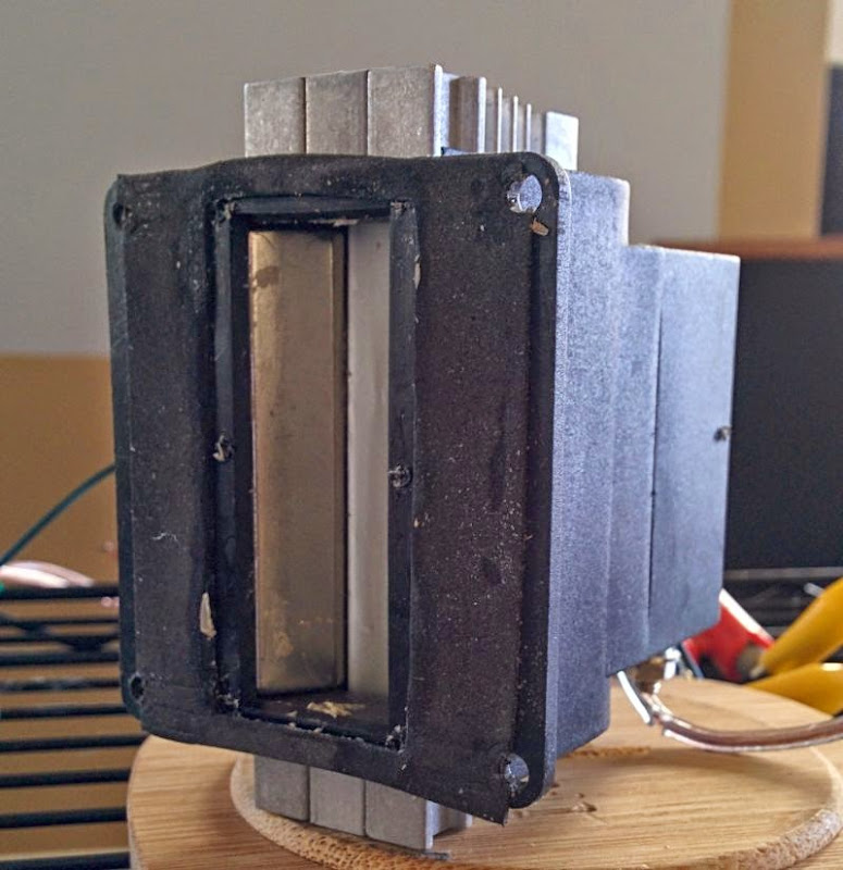
Here's a Fountek NEO CD3.5, with it's horn removed
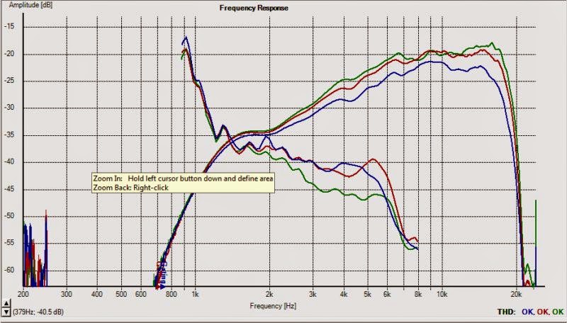
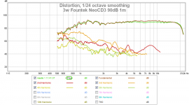
Here's the horizontal polars and the distortion levels of said driver, with a 1uf cap in-line to keep it from exploding
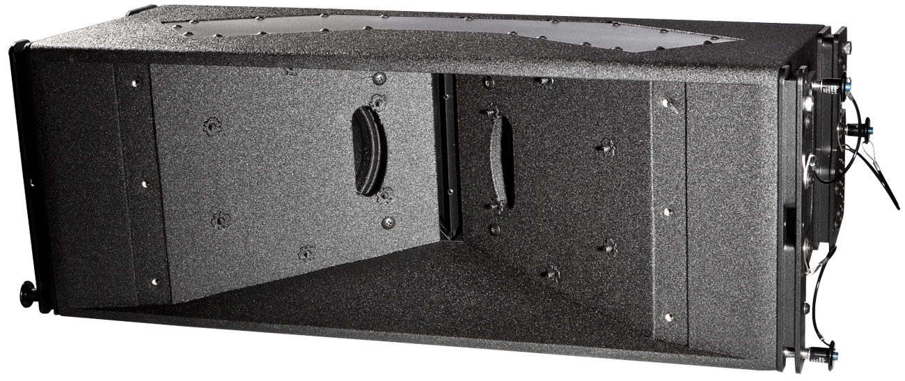
Basically I'm exploring whether it's possible to make a 1/4 scale VTC EL208 with a ribbon at the throat instead of a Paraline. Might offer the benefts of a EL208 (high output, virtual point source, narrow directivity) without the drawbacks of a Paraline (high frequency hash, possible HOMs)
Basically, I have two horns running, and it sounds *excellent*. In fact, this may be one of the best car stereo 'front stages' that I've ever heard.
BUT...
The distortion is an issue. As detailed in the last couple pages, I think the distortion is mostly due to three things:
1) high excursion in the dipole midranges
2) vibration in the horn itself; I didn't realize that these mids would generate so much force!
3) I didn't realize that the shape of the midrange ports had such a huge impact on distortion. So I have a catch-22; use big ports for low distortion and muck up the compression driver. Or vice versa.
I'm definitely not throwing in the towel just yet, but I *am* going to explore alternatives for a few days.
Here's a Fountek NEO CD3.5, with it's horn removed
Here's the horizontal polars and the distortion levels of said driver, with a 1uf cap in-line to keep it from exploding
Basically I'm exploring whether it's possible to make a 1/4 scale VTC EL208 with a ribbon at the throat instead of a Paraline. Might offer the benefts of a EL208 (high output, virtual point source, narrow directivity) without the drawbacks of a Paraline (high frequency hash, possible HOMs)
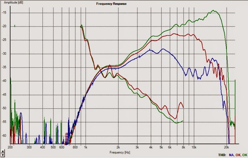
Here's the horizontal polars and distortion.
Yowza, you REALLY gotta aim these carefully. But that could be a good thing for a car or living room, to eliminate reflections off the floor and ceiling.
Next up, the $10,000 question: does the response get completely wrecked by a waveguide? Let's find out...
I can't believe it's been seven days since I updated this thread. Here's where things stand:
Here's the first waveguide I built for this project. Basically it's very narrow, like the Image Dynamics horns, but flipped on it's side. The reason to flip it on it's side is so that horizontal directivity is wide, and vertical directivity is narrow, similar to the directivity patter of the Beolab speakers. (I think this pattern images nicely.)

I abandoned that version of the project, as the frequency response and polars were not good. As illustrated above.
Here's the second version of the project. Same idea, this time using a Pyle PH714.
The second version measured and sounded better than the first. But it was just way too big. The car is basically undrivable, it's like having a bag of groceries stuffed under the dash.
It also didn't sound as good as it measured; not sure why this is, maybe a simple problem of too much EQ. It didn't sound nearly as good as the *third* iteration...
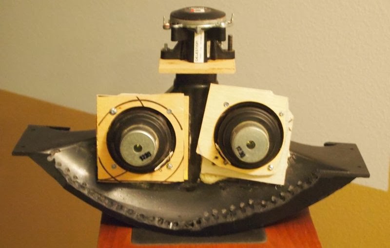
Here's the third iteration of the project. Due to the shallower depth, I was able to cram three midranges onto one horn, and the whole thing still fit under the dash.

This iteration of the project worked really well. It doesn't require much EQ to attain good frequency and polar response. It sounds natural. After a couple weeks worth of work, I'd realized that this project is the closest I've come to actually *finishing* something since my 2009 Unity horn project, the one documented in 'creating the perfect soundstage' over on diyma. (Creating The Perfect Soundstage - Car Audio | DiyMobileAudio.com | Car Stereo Forum)
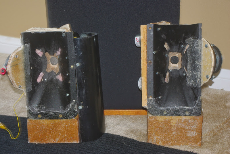
One interesting thing about that project is that the JBL PT waveguide is eerily similar to what I used five years ago. This wasn't intentional; I just noticed when the two were sitting on the bench, their dimensions and coverage angle are basically the same:
^^ Pyle's clone of the JBL PT waveguide
^^ I made these elliptical oblate spheroidal waveguides using Gedde's math. These were in my car in various iterations between 2006 and 2009.
If anyone has the space for these types of waveguides - give it a try. The sound is exceptional. I had them running in stereo in my car for about a week, and the soundstage is as good as I've ever heard in a car. The eeriest part about the whole setup is how the 'space' around the speakers seems to disappear. It doesn't sound anything like your typical car stereo.
I put this project aside, because you guessed it, it was too big. I'm not 100% sure that it will stay on the shelf; it sounds excellent and it wouldn't be impossible to reduce it's foot print. So it's on hiatus.
^^ Here's the fourth iteration. Theoretically this might be the fifth; there's another iteration that I barely even measured or photographed. Basically the idea here was to put the horn under the dash, similar to what most people do in the car.
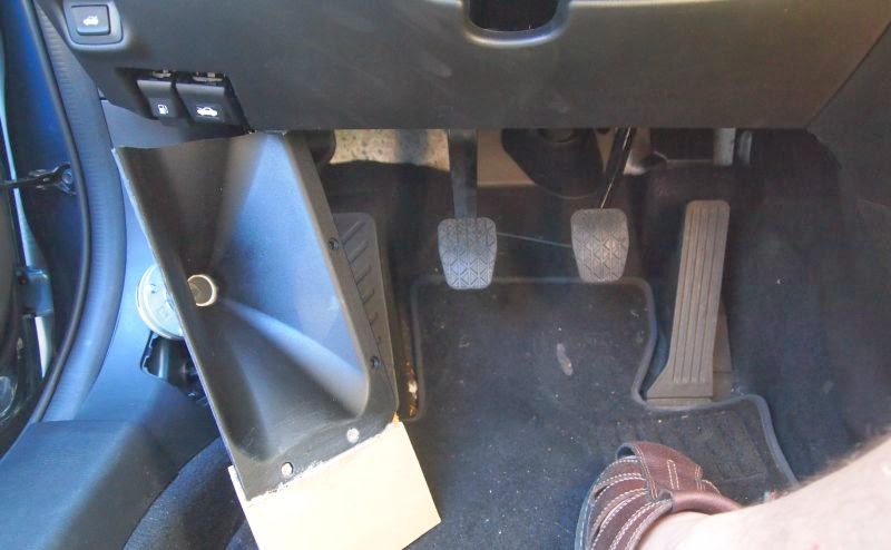
This one measured well, but it's just too big. This one was actually the most cumbersome of all the designs, mostly due to the height. (When you put a waveguide or horn under the dash you have to minimize the height and the width to clear the pedals in the car, and I drive a stick shift which makes things more difficult. When you put the waveguide on the floor, like I did in version 3, there's a lot more space to use.)
Here's the first waveguide I built for this project. Basically it's very narrow, like the Image Dynamics horns, but flipped on it's side. The reason to flip it on it's side is so that horizontal directivity is wide, and vertical directivity is narrow, similar to the directivity patter of the Beolab speakers. (I think this pattern images nicely.)
I abandoned that version of the project, as the frequency response and polars were not good. As illustrated above.
Here's the second version of the project. Same idea, this time using a Pyle PH714.
The second version measured and sounded better than the first. But it was just way too big. The car is basically undrivable, it's like having a bag of groceries stuffed under the dash.
It also didn't sound as good as it measured; not sure why this is, maybe a simple problem of too much EQ. It didn't sound nearly as good as the *third* iteration...
Here's the third iteration of the project. Due to the shallower depth, I was able to cram three midranges onto one horn, and the whole thing still fit under the dash.
This iteration of the project worked really well. It doesn't require much EQ to attain good frequency and polar response. It sounds natural. After a couple weeks worth of work, I'd realized that this project is the closest I've come to actually *finishing* something since my 2009 Unity horn project, the one documented in 'creating the perfect soundstage' over on diyma. (Creating The Perfect Soundstage - Car Audio | DiyMobileAudio.com | Car Stereo Forum)
One interesting thing about that project is that the JBL PT waveguide is eerily similar to what I used five years ago. This wasn't intentional; I just noticed when the two were sitting on the bench, their dimensions and coverage angle are basically the same:
^^ Pyle's clone of the JBL PT waveguide
^^ I made these elliptical oblate spheroidal waveguides using Gedde's math. These were in my car in various iterations between 2006 and 2009.
If anyone has the space for these types of waveguides - give it a try. The sound is exceptional. I had them running in stereo in my car for about a week, and the soundstage is as good as I've ever heard in a car. The eeriest part about the whole setup is how the 'space' around the speakers seems to disappear. It doesn't sound anything like your typical car stereo.
I put this project aside, because you guessed it, it was too big. I'm not 100% sure that it will stay on the shelf; it sounds excellent and it wouldn't be impossible to reduce it's foot print. So it's on hiatus.
^^ Here's the fourth iteration. Theoretically this might be the fifth; there's another iteration that I barely even measured or photographed. Basically the idea here was to put the horn under the dash, similar to what most people do in the car.
This one measured well, but it's just too big. This one was actually the most cumbersome of all the designs, mostly due to the height. (When you put a waveguide or horn under the dash you have to minimize the height and the width to clear the pedals in the car, and I drive a stick shift which makes things more difficult. When you put the waveguide on the floor, like I did in version 3, there's a lot more space to use.)
As you have found, horn/waveguide frequency response and pattern control is always compromised when forced to fit in too small of a space.This one measured well, but it's just too big.
For automotive under or over dash (windshield or rear facing) use, a horizontal line array ("sound bar") using progressive delays on multiple small "full range" drivers to provide beam steering would be my choice for achieving pattern control and wide dynamic range in the limited space available.
The delay required for beam steering could be implemented passively, difficult to predict, but requiring only one channel per side, or with DSP, easier to "dial in" for the desired pattern, but requiring lots of amp channels (one per driver) to work effectively to high frequencies.
With DSP you could also have presets for optimum imaging in the driver's seat, or best imaging for driver and passenger.
As you have found, horn/waveguide frequency response and pattern control is always compromised when forced to fit in too small of a space.
For automotive under or over dash (windshield or rear facing) use, a horizontal line array ("sound bar") using progressive delays on multiple small "full range" drivers to provide beam steering would be my choice for achieving pattern control and wide dynamic range in the limited space available.
The delay required for beam steering could be implemented passively, difficult to predict, but requiring only one channel per side, or with DSP, easier to "dial in" for the desired pattern, but requiring lots of amp channels (one per driver) to work effectively to high frequencies.
With DSP you could also have presets for optimum imaging in the driver's seat, or best imaging for driver and passenger.
Using a boundary to extend the waveguide works well. The reason I don't like using a 'soundbar' type of setup is that the treble sounds all wrong to me. IMHO you want all of the sound originating from a single point, and then expanding to fill the room or the car. It's the same reason I can't listen to line arrays, though I've tried. Even Keele's solution (the CBT) sounds wonky to me. Perhaps I'd get used to it, as I know a lot of people have the same reaction to constant directivity speakers: they sound weird at first.
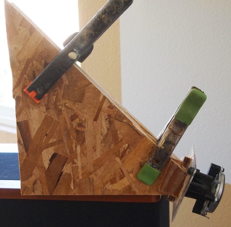
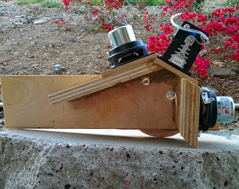
Here's my fourth iteration of this project:
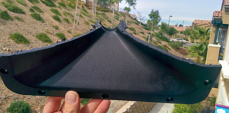

I started out by taking one of Pyle's PT waveguide clones, and sliced it in half. The reason I sliced it in half is that I want to reduce the footprint.

As usual, this is a Synergy horn type of setup. Compression driver at the throat, 5" sealed back midranges tapped into the horn. This time around, I'm not trying to do a cardioid. The cardioid setup sounds wonderful, but those extra drivers eat up a lot of room.
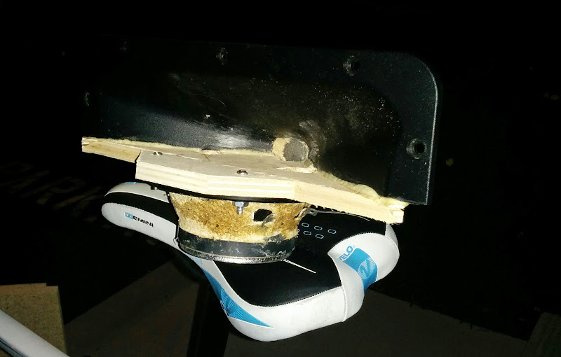
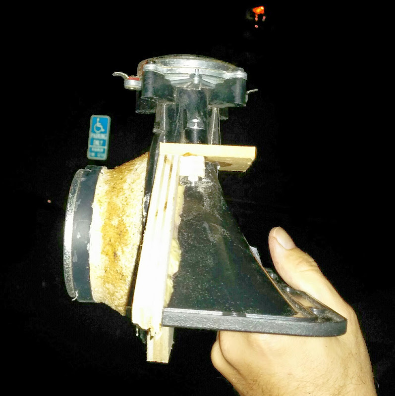
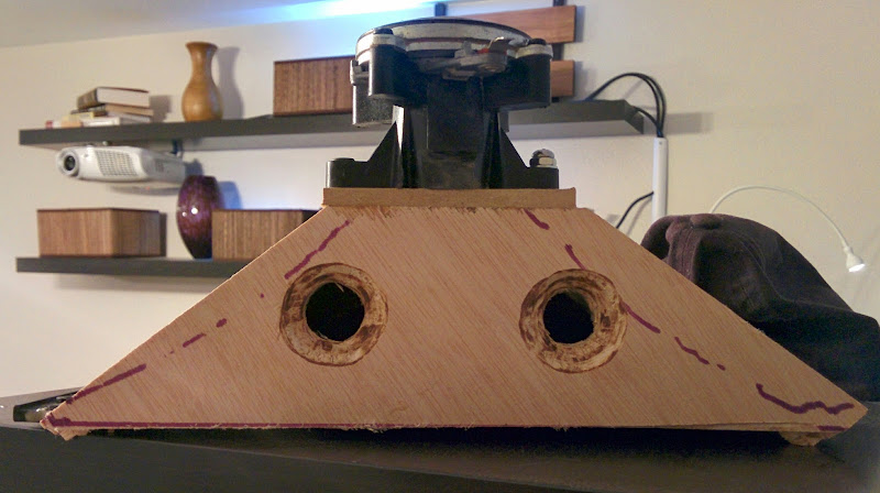
This is pretty close to the finished product. The whole thing took about two or three hours to build, fairly simple process.
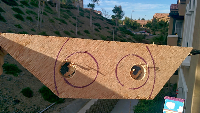
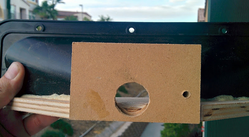
I did one thing differently than Danley does. If you look at the last pic, I've put the midrange about as close to the compression driver as I could get it. The frame of the midrange actually overlaps the compression driver throat, and I even had to cut and file the throat to get the two as close together as possible.
The result of that is simple. In a Synergy or Unity horn, there is a dip that occurs due to the reflection at the throat. That dip sets the upper limit of your midrange. For instance, if you place the midrange four inches from the compression driver, you'll get a dip at approximately 844hz. (speed of sound / divided by 4" / divided by four)
The dip occurs because the midrange energy goes down the throat, hits the compression driver, and is reflected. When the phase rotation is 180 degrees you get a dip.
So that distance is critical; if the midrange is too far away the upper limit of your midrange might be as low as 1000 or even 750hz. In the past I've generally used very small midranges, but small midranges come with their own set of compromises. For instance, in my Unity horn from 2009 I used four 2" midranges. But a single 5" midrange costs less, has more displacement and higher efficiency. And it's just easier to build too.
Another way to get the midrange ultra-close to the tweeter is by using a coaxial, as Danley does in a number of his products. I have some B&C coaxes here in the garage, but the frame is too large for my application. (A 3" coax, like the ones from Kef, might work. I have a few of those too.)
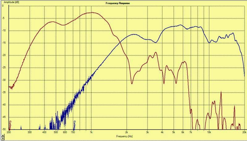
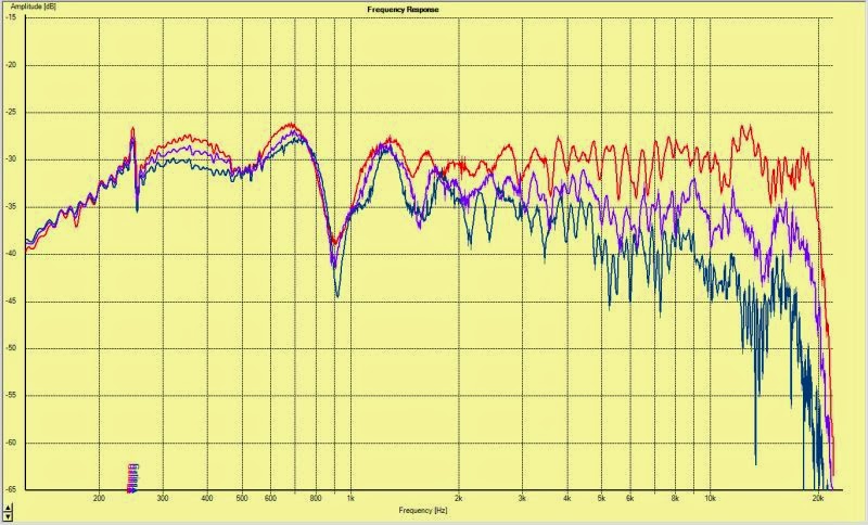
Here's the frequency response of the two drivers. Note that the midrange dip is way up at 2200hz. On the downside, note that the high frequency response is still rolling off. This is inescapable, and is based on the T/S parameters of the driver. IE, your response shape is dictated by T/S params, the only reason I'm placing the mid so close to the compression driver is just to move that midrange dip higher in frequency.
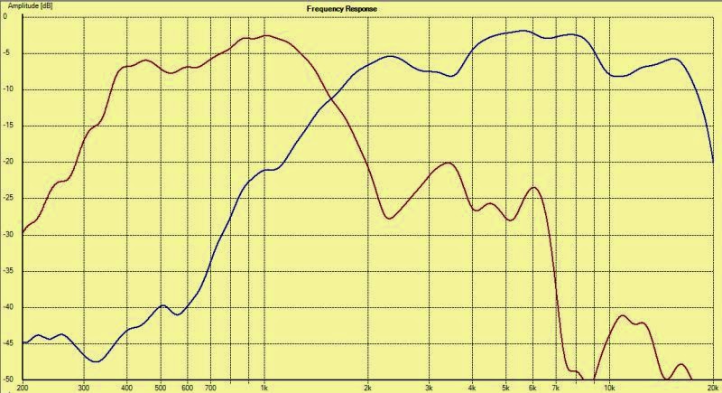
Here's the same response curve, but with the output level of the compression driver increased by six decibels, and sixth octave smoothing applied to both drivers. These curves do not use any EQ at all. The entire crossover is a single cap, just used to reduce output level and to flatten out the falling response of the compression driver.
The result of that is simple. In a Synergy or Unity horn, there is a dip that occurs due to the reflection at the throat. That dip sets the upper limit of your midrange. For instance, if you place the midrange four inches from the compression driver, you'll get a dip at approximately 844hz. (speed of sound / divided by 4" / divided by four)
The dip occurs because the midrange energy goes down the throat, hits the compression driver, and is reflected. When the phase rotation is 180 degrees you get a dip.
So that distance is critical; if the midrange is too far away the upper limit of your midrange might be as low as 1000 or even 750hz. In the past I've generally used very small midranges, but small midranges come with their own set of compromises. For instance, in my Unity horn from 2009 I used four 2" midranges. But a single 5" midrange costs less, has more displacement and higher efficiency. And it's just easier to build too.
Another way to get the midrange ultra-close to the tweeter is by using a coaxial, as Danley does in a number of his products. I have some B&C coaxes here in the garage, but the frame is too large for my application. (A 3" coax, like the ones from Kef, might work. I have a few of those too.)
Here's the frequency response of the two drivers. Note that the midrange dip is way up at 2200hz. On the downside, note that the high frequency response is still rolling off. This is inescapable, and is based on the T/S parameters of the driver. IE, your response shape is dictated by T/S params, the only reason I'm placing the mid so close to the compression driver is just to move that midrange dip higher in frequency.
Here's the same response curve, but with the output level of the compression driver increased by six decibels, and sixth octave smoothing applied to both drivers. These curves do not use any EQ at all. The entire crossover is a single cap, just used to reduce output level and to flatten out the falling response of the compression driver.
Last edited:

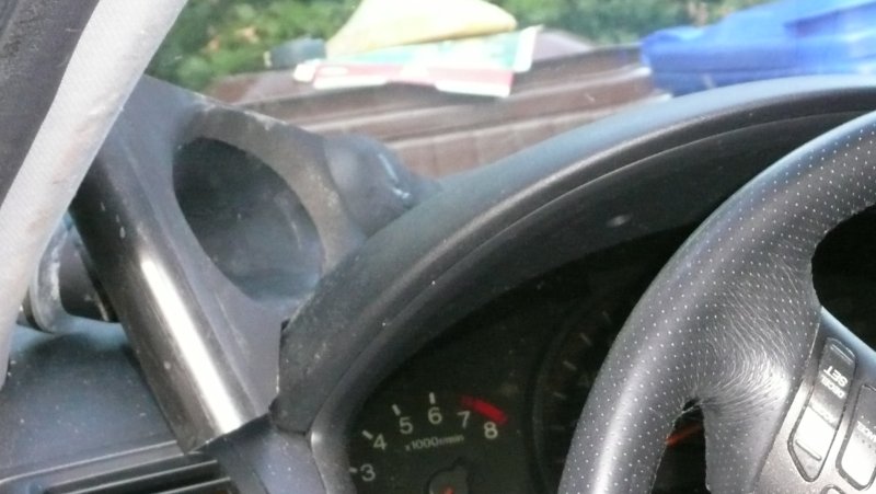
Here's a pic of my 2009 setup. This sounded very good. It used the slope of the windshield and dash to extend the waveguide. Note how the edge and angle lines right up.
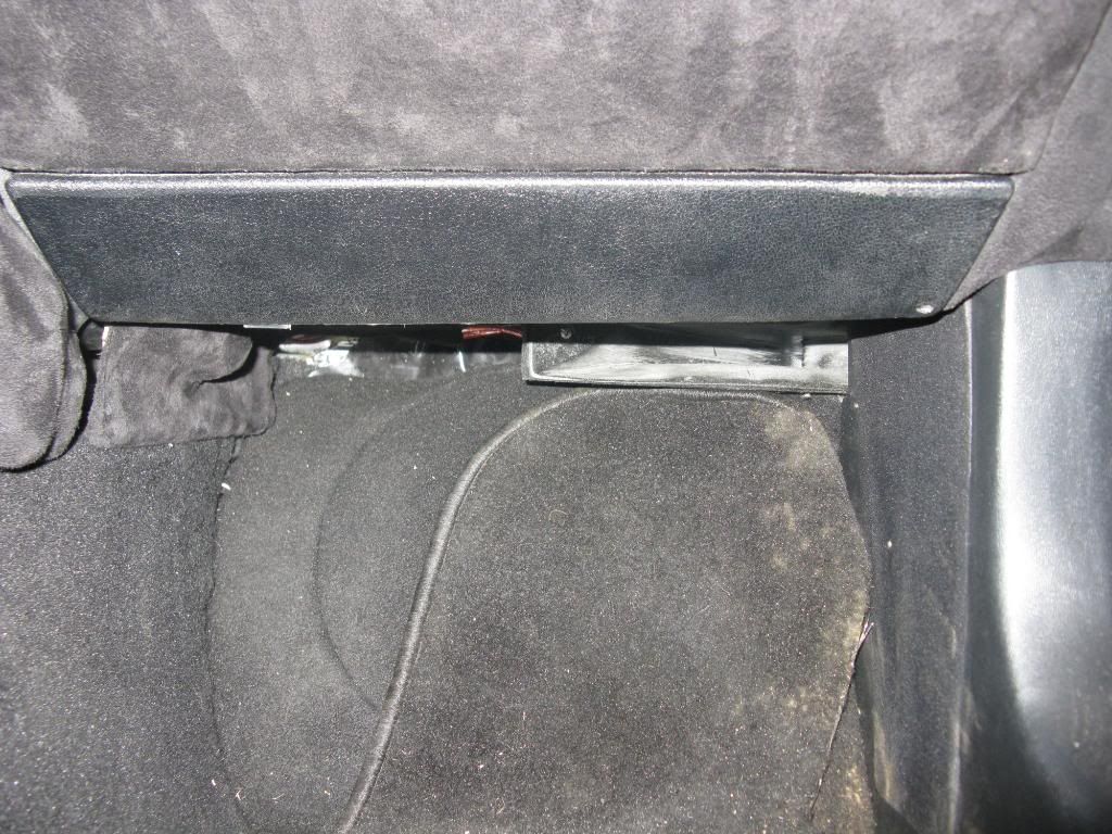
Here's Mic Wallaces BMW. I've never heard it, but it's won a bunch of competitions. It's one of the few cars I've seen where the waveguides are waaaaay back. His waveguides are nearly flush with the firewall.
I'm basically gunning for something similar. To use the corner of the car to extend the waveguide.
Here's some reasons I think this might work well:
1) I think "seeing" your speakers really has an impact on the soundstage. I really find that speakers stage better when you can't see them. Having the speakers on the dash is distracting in that respect. When I had version 3 of this project on the floor of the car, I was surprised by how high the soundstage was.
2) Ideally I'd use a cardioid, but since I can't make the space for it, I think that pushing the waveguides as far back as possible should reduce the effect of sound re-radiated by the rear wall. Or at least that's the idea. Seems to work for Mic.
I've been experiencing a bit of a 'gut check' with this project.
Basically, I have two horns running, and it sounds *excellent*. In fact, this may be one of the best car stereo 'front stages' that I've ever heard.
BUT...
The distortion is an issue. As detailed in the last couple pages, I think the distortion is mostly due to three things:
1) high excursion in the dipole midranges
2) vibration in the horn itself; I didn't realize that these mids would generate so much force!
3) I didn't realize that the shape of the midrange ports had such a huge impact on distortion. So I have a catch-22; use big ports for low distortion and muck up the compression driver. Or vice versa.
I'm definitely not throwing in the towel just yet, but I *am* going to explore alternatives for a few days.
Here's a Fountek NEO CD3.5, with it's horn removed
Here's the horizontal polars and the distortion levels of said driver, with a 1uf cap in-line to keep it from exploding
Basically I'm exploring whether it's possible to make a 1/4 scale VTC EL208 with a ribbon at the throat instead of a Paraline. Might offer the benefts of a EL208 (high output, virtual point source, narrow directivity) without the drawbacks of a Paraline (high frequency hash, possible HOMs)
Very cool
") I'm surprised the neo3.5 measures so well in its " naked " state!
I'm surprised the neo3.5 measures so well in its " naked " state!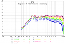
With the big horns, I don't know where you would put the midbasses. And I would think you would want something substantial to go with the horns.
I think a nice 8" coax with the proper crossover would do as much or more than what you are working on. You could even get pattern control lower than the 8" cone by making a 10 or 12" waveguide in front of the speaker like Tom does on his small coaxes. Couple of rings with a 45 degree bevel would get you there and quick. And be more shallow than the horn with output to 100 atleast given cabin gain. The waveguide loading of the midrange might help flatten out the FR where cabin gain picks up at giving you a nice boost in sensitivity across the board too.
I think a nice 8" coax with the proper crossover would do as much or more than what you are working on. You could even get pattern control lower than the 8" cone by making a 10 or 12" waveguide in front of the speaker like Tom does on his small coaxes. Couple of rings with a 45 degree bevel would get you there and quick. And be more shallow than the horn with output to 100 atleast given cabin gain. The waveguide loading of the midrange might help flatten out the FR where cabin gain picks up at giving you a nice boost in sensitivity across the board too.
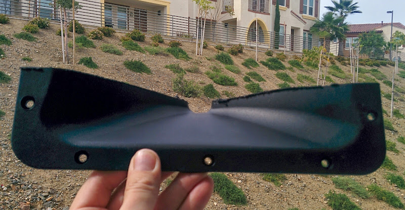
This afternoon, I am working on a proper waveguide for the Fountek NEO 3.5H. The 'stock' waveguide isn't bad at all, but I wanted to make a bigger one, because I wanted to unitize it of course.
If anyone's in a similar spot, the 'exit angle' of the NEOCD 3.5H, with the stock waveguide removed, is fifty three degrees.
- Status
- This old topic is closed. If you want to reopen this topic, contact a moderator using the "Report Post" button.
- Home
- Loudspeakers
- Multi-Way
- Edge of No Control