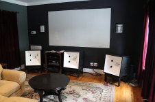
Sometime last year I became totally enamored by the Synergy Horn concept after several "a-ha" moments about how Tom Danley's other inventions work (Paraline, and Tapped Horn.) My S.O. (the bestest wife in the whole wide world) gave me permission to build a set of three for the LCR of our home theater. After many...many prototypes, rebuilds, back-tracks and a few choice words they are mostly done. I have Tom's permission to post details of my design, as it's his idea and he has it very well covered by patents.
First...for those that haven't heard a well designed DIY Synergy Horn, or the real deal. Find some. Now. They really are that special. I have a degree in Electrical Engineering and have designed audio equipment professionally on/off for over 20 years. They image better than any other speaker, and there is a precision and clarity that some of the crazy high end magnesium/beryllium/unobtanium based speakers can't match.
So, without further ado here are the basics for each speaker:
4 Dayton Classic 8" woofers, 295-310
4 Dayton Designer Series 3" woofers, 295-422
1 PRV Audio D290Py-B, 294-2833
22.5" Cube
60x60 Coverage Area
45Hz to 18kHz +/-3dB (ish)...more on that later.
I'll be posting the photo's I took during the build and my drawings...but it's going to take some time to put together all the info...so patience is appreciated. Questions are welcome at any time.
Scott
Attachments
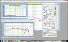
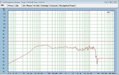
Next up are some frequency response plots. I designed the speaker using SoundEasy V18, a Dayton Microphone and a custom jig I designed. SoundEasy is one of the best values...but also one of the quirkiest pieces of software I've ever used.
The on/off axis plots were measured with a real speaker in slightly different conditions than were used to measure the individual drivers for crossover development. I believe I might have some early reflections from a compost pile, trash can and garage door creeping in the on-off axis plots (taken at 0-10-20-30-45 degrees) which I didn't have for the measurements used for crossovers. Those were taken in a very large wide open band hall.
Scott
Attachments
Scott,The on/off axis plots were measured with a real speaker in slightly different conditions than were used to measure the individual drivers for crossover development.
Response looks great, surprising amount of low end for a sealed (I assume) enclosure.
What was the cabinet distance from the ground in the off axis measurements?
Have you done any sensitivity or phase measurements?
22.5" wide, that would only cover up 6" of the window by my speaker position...
Art
Scott,
Response looks great, surprising amount of low end for a sealed (I assume) enclosure.
What was the cabinet distance from the ground in the off axis measurements?
Have you done any sensitivity or phase measurements?
22.5" wide, that would only cover up 6" of the window by my speaker position...
Art
It was a ground plane measurement. Ignore sensitivity though...that's not absolute, relative it's good, no gains were changed.
The Dayton woofers work well in a moderately sized sealed enclosure. I have phase measurements...but they aren't quite where I want them. The crossover still needs some fine tuning. I have plenty of overlap in the drivers, and where I was really good at notch filtering using LSPCad Pro 5.0...in Windows 7 and SoundEasy I find the interface annoying and need to revisit. I still have the tweeter leading the mids/woofs by a small amount.
Scott
Ground plane would explain the LF .It was a ground plane measurement.
The crossover still needs some fine tuning.
I was hoping you had designed passive crossovers we could copy, oh well..
Ground plane would explain the LF .
I was hoping you had designed passive crossovers we could copy, oh well..
They are passives...and I'll post the current schematic. Just realize there are more things that can be done to improve phase response. And the crossover may change.
I have tons of driver overlap, and yet I'm still dealing with 2'nd order or higher acoustic rolloff too close to crossover frequency. I found SoundEasy much more difficult to play with phase than LSPCad...I may fire up my old XP box to do the crossover in LSPCad and import it into SoundEasy for tuning...still not decided.
Scott
Scott,They are passives...and I'll post the current schematic. Just realize there are more things that can be done to improve phase response. And the crossover may change.
I misunderstood, the response you posted using passive crossovers appears as smooth as any of the DSL Synergies, impressive.
")
The PRV Audio D290Py-B looks like a very affordable well performing compression driver. Glad to see people trying new products. Nice job!
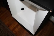
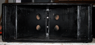
Yeah, it works really well. I couldn't bring myself to spend the $ on the BMS most seem to use. When I post the construction pics I'll show how I made it easy to physically swap drivers. At 60x60 you have to do some interesting things using the normal method of 1/4 mounting plate and the 2 bolt pattern. The PRV has a cast aluminum back cup which is one of the requirements for the method I used.
Scott
One of the bigger difficulties for starting a project like this is figuring out how to build the speaker. I had a few rules I set out for myself:
1. Do something where the back cup design for the midrange speaker is relatively easy to implement. I had a version where I was turning 6" burial grade conduit on my lathe. Not cool. Pain in the rear really. Many different closed back speakers will work, but a lot of them are relatively large (5" diameter plus) making placement near the tweeter a bit more challenging.
2. All drivers needed to be nearly vertical. The suspensions of a lot of home drivers will take a set over time if stored horizontal...I've seen it way too often. Since I'm using relatively inexpensive drivers I wanted to avoid this since I don't plan on building myself new speakers every 5 years or so.
3. The outside size limit was set by what my S.O. is willing to live with...and frankly they are pushing the boundary.
4. The enclosure needed to have access ports on the sides and back so that I could get to the internal wiring and drivers. I tried a version where I bolted the horn into a box...but I couldn't ever get the box braced very stiffly.
So...that said I decided that all drivers would be mounted on the two vertical side walls of the horn...and that those walls would run from top to bottom aiding with the bracing.
When building one of these horns the important thing to realize is that you're building a compound mitered box. My favorite is at: Compound Angle Calculator ::: Mitered and Butted Joints
You could do all of the calculations by spreadsheet and there are plenty available for download. The above calculator is handy because it assumes you'll be using a table saw and tries to make sure you can run every piece flat on the saw. (You might have to flip something over....)
I've attached the drawings I used as a guide. There is one that I'll post more detail, and that is the one I used to create a template to mark driver mounting holes, entry ports, surround clearance routing...etc.
One very important thing to note about doing something like this without having the aid of a CNC router to machine all your parts.
Tolerance errors stack up...work slowly, carefully and don't panic. Each speaker will end up slightly different. Work to fit the parts to the project, not build all the parts and hope they go together. This is something I learned when building fine furniture. My three speakers vary by up to 1/16" of an inch in some dimensions.
Scott
Attachments
Scott,2. All drivers needed to be nearly vertical. The suspensions of a lot of home drivers will take a set over time if stored horizontal...I've seen it way too often. Since I'm using relatively inexpensive drivers I wanted to avoid this since I don't plan on building myself new speakers every 5 years or so.
This is a point that too many overlook, especially younger people who have not owned speakers long enough to realize that horizontal cones can sag several millimeters in just a few years.
The baffle board vertical dimension is missing, I assume it to be 21"?
As the OP, you can edit the OP forever, you might start an index, "plans in post # 12 and ___, Hornresp inputs in post #__" etc."
Did you try rounding the speaker port holes?
Art
Thanks for posting this info! Nice build. Good bandwidth for such small size.
I think I would have made the fronts black for a HT setting but just an insignifiant comment from the peanut gallery
Jim
When I finish the grills they will be black. I wanted something with a bit more pizazz with the grills off.
Scott
Scott,
This is a point that too many overlook, especially younger people who have not owned speakers long enough to realize that horizontal cones can sag several millimeters in just a few years.
The baffle board vertical dimension is missing, I assume it to be 21"?
As the OP, you can edit the OP forever, you might start an index, "plans in post # 12 and ___, Hornresp inputs in post #__" etc."
Did you try rounding the speaker port holes?
Art
Correct, the "action" area of the horn is 21"x21".
Thanks for the tip on editing the opening post...I'll have to do that.
What do you mean by rounding? They have frustrum's cut into them...I tried many different versions. I didn't try to cut the ovals that some people use.
Scott
Your speaker exit holes look like they have a 90 degree hard edge, I used a 1/8" round over for the holes in my Paraline 2x8" cabinets to reduce potential chuffing noise and HF reflections.What do you mean by rounding? They have frustrum's cut into them...I tried many different versions. I didn't try to cut the ovals that some people use.
Attachments
Your speaker exit holes look like they have a 90 degree hard edge, I used a 1/8" round over for the holes in my Paraline 2x8" cabinets to reduce potential chuffing noise and HF reflections.
I did not try that...Danley doesn't seem to use them on his...and I wanted to minimize the area of discontinuities in the horn mouth.
Scott
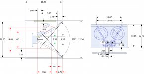
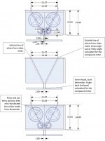
One of the things I see folks struggling with is how to place the holes for the entry ports...and figure out the size/shape of the pieces for the compound mitered box.
Hopefully this set of drawings helps simplify it.
This doesn't get into 1/4 wavelength spacing...it doesn't get into cutoff or flare-rate...it just makes sure the holes end up where you want them and don't hit the side of the box.
So the coverage angle sets the initial angles...in my case 60x60...but the method works for any desired angle. The tweeter size sets the throat dimension which is where you need to start. In my case I'm using a 1" compression driver so I wanted a 1"x1" throat for the horn. I've seen that Danley's speakers don't smooth out the throat entry, but I keep reading that the entry is critical for hi-fi. I figured out a relatively easy way to get it smoothed and I'll go into that later.
The first drawing is the completed placement of drivers, drawn to scale, and port holes...but it's complicated. I've got a bunch of other dimensions in there that I was using as an aid during construction.
The second drawing shows the lines of where the inside of the horn would fall, the outside if the horn if it were butt jointed and the sides didn't extend...and the outside line of the pieces of the horn that are butt jointed.
One thing to remember with this compound miter...the outsides are smaller than the inside for the cut pieces...you have to angle them back as the pieces rotate out. It's tough to explain, but you'll see it if you cut some test pieces.
Which brings me to another very important point.
For all that is good and holy, cut some test pieces. Don't be afraid. Cut lots....figure out how this goes together on smaller cheap scrap. You'll save yourself a lot of trouble.
Attachments
- Home
- Loudspeakers
- Multi-Way
- Synergy Horns-Dayton and PRV.....