This is perhaps the best story with measurements of a line array go to kimmosto's diy archive and select KS-160-21
Keele's origila paper can be found at www.audioartistry.com and here we see that shading is important
Keele's origila paper can be found at www.audioartistry.com and here we see that shading is important

Lines need shading delay on curve to sum well, we can see that Kommosto's straight line with no delays exhibits bad vertical lobing with very small offset. His xo was 3300, way too high!
I don't think long fullrange lines suit homes at all unless
- they are curved or straight with delays
- they use fullranges or coaxial 2-way drivers to prevent horizontal lobing
A curved or delayed line has very strong directivity sideways because of it creates
cancellations. Radiation pattern must be like a dipole without back radiation.
Ooops, I meant this
Lines need shading delay or curve to sum well
Kimmosto's line is 200cm high and rooms here at 250-260cm. I think it works as infinite line in a room. He doesn't show horizontals but says that there is bad lobing. Overall they were really good speakers, but didn't deliver the bass mode control that he wanted
Last edited:
That particular array (KS-160-21) has a tweeter line that is not floor to ceiling in length. The tweeter line isn't anywhere near 200 cm.
I've read a lot of material on line arrays and most boil down to this:
Floor to ceiling line array: not advised to use shading.
Shorter array: shading is needed.
A lot can be found on this forum, look for posts by "speaker dave" among others:
http://www.diyaudio.com/forums/multi-way/165596-constant-beam-width-transducers-line-arrays-13.html#post2344178
So I don't really agree with this without further information:
By the way, don't show Keele's papers as that piece of information because he uses the mirror floor image to enhance the CBT performance but in the straight line example there's no mention of either the floor or ceiling mirror effect.
The strangest design choice of the CBT to me is that it mimics a point source that is coming from the floor level. I've been told it does not sound that way but to be sure I'd consider hanging it from the ceiling, or better yet, do what Geddes once said and put it on it's side and hang it in the corners:
http://www.diyaudio.com/forums/multi-way/177403-linkwitz-orions-beaten-behringer-what-179.html#post3411297
I've read a lot of material on line arrays and most boil down to this:
Floor to ceiling line array: not advised to use shading.
Shorter array: shading is needed.
A lot can be found on this forum, look for posts by "speaker dave" among others:
http://www.diyaudio.com/forums/multi-way/165596-constant-beam-width-transducers-line-arrays-13.html#post2344178
So I don't really agree with this without further information:
Lines need shading delay or curve to sum well
Kimmosto's line is 200cm high and rooms here at 250-260cm. I think it works as infinite line in a room. He doesn't show horizontals but says that there is bad lobing. Overall they were really good speakers, but didn't deliver the bass mode control that he wanted
By the way, don't show Keele's papers as that piece of information because he uses the mirror floor image to enhance the CBT performance but in the straight line example there's no mention of either the floor or ceiling mirror effect.
The strangest design choice of the CBT to me is that it mimics a point source that is coming from the floor level. I've been told it does not sound that way but to be sure I'd consider hanging it from the ceiling, or better yet, do what Geddes once said and put it on it's side and hang it in the corners:
http://www.diyaudio.com/forums/multi-way/177403-linkwitz-orions-beaten-behringer-what-179.html#post3411297
Last edited:
New driver.... New rules?
I am still experimenting with full range driver single column arrays (as well as twin and triple column ) and finding that one over riding factor counts more than any other.
When using full range drivers the power response is crucial ie A very even on and off axis response out to plus minus 90 degrees is the key.
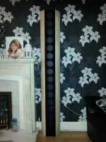
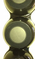
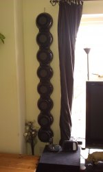
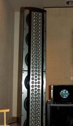
Using a version of the 4.5 inch Neo magnet BMR driver I have been getting great results, esp when used in very shallow curved wall cabinets which can hang on the wall. ( See pics)
Also the min height is interesting....It is less important than driver choice for sure. But the 1.6m tall ( 8 driver version) sounded identical in terms of imaging, 3D accuracy, texture, detail etc Vs the 1.8m tall ( 16 driver version) , but the 16 driver version could go louder with lower distortion and was more sensitive....
All simply a function of more Sd... Double the surface area of cone moving and you half the distance it needs to move for a given SPL / distortion.
Even increasing the driver to driver centre spacing has no audible in room effects ( slight measurable differences) ie 112mm tight spacing Vs 210mm spacing with the dome array's.
The bottom line is that the unique ability of the BMR to sound and measure within a couple of Db from on axis to plus / minus 80 to 90 degrees ( giving almost perfect 160 to 180 degree coverage when wall mounted) is changing the way domestic line arrays can perform in real world rooms.
Still learning and experimenting but the sonic results are so good I am now in the strange position that I will have designed something that sounds better than anything else I have ever built and yet I don't fully understand exactly how it works...!!
Cheers
Derek.
I am still experimenting with full range driver single column arrays (as well as twin and triple column ) and finding that one over riding factor counts more than any other.
When using full range drivers the power response is crucial ie A very even on and off axis response out to plus minus 90 degrees is the key.
Using a version of the 4.5 inch Neo magnet BMR driver I have been getting great results, esp when used in very shallow curved wall cabinets which can hang on the wall. ( See pics)
Also the min height is interesting....It is less important than driver choice for sure. But the 1.6m tall ( 8 driver version) sounded identical in terms of imaging, 3D accuracy, texture, detail etc Vs the 1.8m tall ( 16 driver version) , but the 16 driver version could go louder with lower distortion and was more sensitive....
All simply a function of more Sd... Double the surface area of cone moving and you half the distance it needs to move for a given SPL / distortion.
Even increasing the driver to driver centre spacing has no audible in room effects ( slight measurable differences) ie 112mm tight spacing Vs 210mm spacing with the dome array's.
The bottom line is that the unique ability of the BMR to sound and measure within a couple of Db from on axis to plus / minus 80 to 90 degrees ( giving almost perfect 160 to 180 degree coverage when wall mounted) is changing the way domestic line arrays can perform in real world rooms.
Still learning and experimenting but the sonic results are so good I am now in the strange position that I will have designed something that sounds better than anything else I have ever built and yet I don't fully understand exactly how it works...!!
Cheers
Derek.
Attachments
Derek,
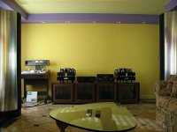
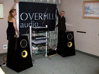
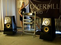
Have you ever tried a Beveridge like setup with the arrays on the long wall facing each other?

Source of picture: http://cgim.audiogon.com/cgi-bin/vs.pl?vevol&1221936782&viewitem&19&showall
Have you ever tried a Beveridge like setup with the arrays on the long wall facing each other?
Source of picture: http://cgim.audiogon.com/cgi-bin/vs.pl?vevol&1221936782&viewitem&19&showall
Attachments
Last edited:
Beverage
Hi wesayso,
Not really , I have one pair of on wall arrays either side of the fire place which I use for two channel music, they fire across the short ( 4.5 meter width) dimension of the room.
Also have 2 more pairs in the same room for the home cinema set up, firing up and down the 5.5m length of the room.
I have had several folks comment that music still sounds great 90 degrees of axis ie on the home cinema sofa, and also guys on the two channel sofa still get a fab home cinema sound...
Don't think its Beverage related just very broad and even off axis coverage.
Cheers
D.
Very lucky!
Hi Wesayso,
Yes I am very, very lucky being blessed with an understanding beautiful wife...Also she loves music and movies so is happy to have lots of on wall arrays as well as the various electronics required !!
Cheers
Derek.
Hi Wesayso,
Yes I am very, very lucky being blessed with an understanding beautiful wife...Also she loves music and movies so is happy to have lots of on wall arrays as well as the various electronics required !!
Cheers
Derek.
Attachments


From what I understand without curving one experiences beaming. And how does one avoid rapid variation of sound pressure with this idea?
By the way, I think you will be really pleased with CBT36. Even with it's cheap dome tweeters and its low sensitivity, it completely blows away the treble response that Abbey with B&C DE250 compression driver offers. No comparison.
The difference with better drivers in a CBT design isn't said to be that great. The multiple drivers and DSP crossover tend to even the playing field. But then, I wouldn't mind better drivers with higher sensitivity either. Who knows for sure how much the difference is in a good room with top electronics. The nice thing about the design below is that one can change drivers easily ("drawers" in the back). A little expensive maybe to try out a lot....

One could build a one-way CBT with 2" drivers too. That should improve the horizontal polar response. But then, it's already darn good it you look the indenpendent polar plot of the prototype. I wouldn't put to much emphasize on the CBT36 vs B&W measurements. They are conducted in a regular room with no treatment, uneven floor and very little smoothing. No one else then Don shows data of their speakers like that!
As you know, I'm a little biased here.")
By the way, I think you will be really pleased with CBT36. Even with it's cheap dome tweeters and its low sensitivity, it completely blows away the treble response that Abbey with B&C DE250 compression driver offers. No comparison.
The difference with better drivers in a CBT design isn't said to be that great. The multiple drivers and DSP crossover tend to even the playing field. But then, I wouldn't mind better drivers with higher sensitivity either. Who knows for sure how much the difference is in a good room with top electronics. The nice thing about the design below is that one can change drivers easily ("drawers" in the back). A little expensive maybe to try out a lot....
One could build a one-way CBT with 2" drivers too. That should improve the horizontal polar response. But then, it's already darn good it you look the indenpendent polar plot of the prototype. I wouldn't put to much emphasize on the CBT36 vs B&W measurements. They are conducted in a regular room with no treatment, uneven floor and very little smoothing. No one else then Don shows data of their speakers like that!
As you know, I'm a little biased here.
These JBL's CBT pages are worth studying. Notice the placement of tweeters in the big one! JBL :: Product Family
A clasic diy-CBT is a curve with just HiVi B3S drivers. Not much output below 100Hz - room for a sub!
A clasic diy-CBT is a curve with just HiVi B3S drivers. Not much output below 100Hz - room for a sub!
An externally hosted image should be here but it was not working when we last tested it.
The trick is to get the crossover point as low as possible and the mids as close to the tweeter as possible.
It is not THE trick but ONE trick of many others.
You have two problems to solve in the horizontal domain when tweeter and midrange are placed side by side:
1) the beaming of the midrange and the near-omni behaviour of the tweeter at crossover
2) the lobing at crossover
Solutions to 1):
a) use a small midrange
b) low crossover point (where the midrange doesn't beam yet)
c) use a waveguide on the tweeter
Solutions to 2):
d) place midrange and tweeter as close as possible (aka use a small midrange
)e) low crossover point
f) steep filtering
Of course, a) and d) are the same except that d) requires a small tweeter, too, but that is no problem. b) and e) are also the same.
For passive speakers I would recommend Solution a)/d). A low crossover point is not usable with all tweeters, because not matter how many you use in parallel it is not a good idea to drive them near or even below their resonance frequency. Even if you don't get problems with DC-Displacement because of the low driving voltage for each tweeter, you will most probably get problems because no tweeters impedance is the same, and so they will drift away from each other, and that may cause BIG problems.
I am interested in vertical polars of a floor to ceiling line array. Does anyone have them?
A polar is not the right diagram of such an array. A 2D-Map is better. I can simulate you one, with ideal point sources or real drivers*, with ideal or absorbing reflection from floor or ceiling (absorbing only frequency-independent).
*read "real" as "simulated by a disc"
Help with sim
Hi Baseballbat,
If you have some time to spare it would be great if you could run a simulation for me. Assume a 1.8 meter tall array of 4.5 inch divers( Sd of 50) with 112mm centre to centre spacing and zero beaming over plus / minus 80 degrees ( ie perfect 160 degree coverage).
Each driver 4 Ohm, wired in 4 groups of 1 Ohm for a total of 4Ohm impedance. Fs is 100Hz but using Eq to boost the low end. All drivers running full range, no sub in this sim. Optional sub crossed over at 70Hz.
Thanks in advance for your help.
Cheers
Derek.

Hi all,
It has been a while since there were activity on this thresd. I in the mean time I found this quote by Tom Danley, a strong advocate of point sources:
A true line array has so many problems related to it’s geometry (unless one made one floor to ceiling) that the need to be shaped, curved or tapered in amplitude to make them behave more like a point source.
http://www.diyaudio.com/forums/multi-way/217298-square-pegs-55.html#post3679767
This is still just another anecdote, no proof that the floor to ceiling line source would work like it is "infinite".
Hi Baseballbat!
I would very much be interested in a 2D map if you could provide such. The horizontal behaviour is not of much interest since it would be similar in both a CBT and a straight array. Please use "ideal drivers" and perfect roof and floor (concrete?).
If you prefer real world drivers, have look at the Wisdom LS4. Close CTC spacing, narrow tweeter and low cross over point (750 hz). http://wisdomaudio.com/products_wisdom-ls4-ls3.php
Thanks,
Jan Egil
It has been a while since there were activity on this thresd. I in the mean time I found this quote by Tom Danley, a strong advocate of point sources:
A true line array has so many problems related to it’s geometry (unless one made one floor to ceiling) that the need to be shaped, curved or tapered in amplitude to make them behave more like a point source.
http://www.diyaudio.com/forums/multi-way/217298-square-pegs-55.html#post3679767
This is still just another anecdote, no proof that the floor to ceiling line source would work like it is "infinite".
It is not THE trick but ONE trick of many others.
You have two problems to solve in the horizontal domain when tweeter and midrange are placed side by side:
1) the beaming of the midrange and the near-omni behaviour of the tweeter at crossover
2) the lobing at crossover
Solutions to 1):
a) use a small midrange
b) low crossover point (where the midrange doesn't beam yet)
c) use a waveguide on the tweeter
Solutions to 2):
d) place midrange and tweeter as close as possible (aka use a small midrange
e) low crossover point
f) steep filtering
Of course, a) and d) are the same except that d) requires a small tweeter, too, but that is no problem. b) and e) are also the same.
For passive speakers I would recommend Solution a)/d). A low crossover point is not usable with all tweeters, because not matter how many you use in parallel it is not a good idea to drive them near or even below their resonance frequency. Even if you don't get problems with DC-Displacement because of the low driving voltage for each tweeter, you will most probably get problems because no tweeters impedance is the same, and so they will drift away from each other, and that may cause BIG problems.
A polar is not the right diagram of such an array. A 2D-Map is better. I can simulate you one, with ideal point sources or real drivers*, with ideal or absorbing reflection from floor or ceiling (absorbing only frequency-independent).
*read "real" as "simulated by a disc"
Hi Baseballbat!
I would very much be interested in a 2D map if you could provide such. The horizontal behaviour is not of much interest since it would be similar in both a CBT and a straight array. Please use "ideal drivers" and perfect roof and floor (concrete?).
If you prefer real world drivers, have look at the Wisdom LS4. Close CTC spacing, narrow tweeter and low cross over point (750 hz). http://wisdomaudio.com/products_wisdom-ls4-ls3.php
Thanks,
Jan Egil
- Status
- This old topic is closed. If you want to reopen this topic, contact a moderator using the "Report Post" button.
- Home
- Loudspeakers
- Multi-Way
- Floor-to-ceiling array vs CBT