I have been planning on building a waveguide for some Dayton soft dome tweeters in an attempt to lower their acceptable crossover frequency.
In retrospect I see that I should have bought ND20's, but I bought ND16's so I am stuck with 48 of those.
I have seen pictures of waveguides with ND20's that are hogged out of solid wood and in one case it appears to be a large solid handrail for stairs.
.
I decided to make my design modular, where I glue several sections together to get the final shape.
This way the tweeter mounting holes are in a flat 7/8" thick sheet of wood.
I also am making the holes blind so that the C to C spacing can be as small as possible without the wood falling apart. No rib left between units, so C to C is 32.5 mm.
I will run the wires out a 1/4" hole in the center of the mounting hole and also use this to push out any defective units. I have a step drill to drill the profile and will use a Bridgeport mill to maintain C to C and straightness of the line.
.
Now, my question:
I see some very sophisticated waveguide shapes on various forums, but all the linear waveguides seem to be simple 45 degree angles.
Can I gain anything by using a more exponential (or simply different)shape?
.
To the people that know, do you think I could cross over ND16's at 2 kHz (LR4) if the power to each tweet was only maybe 1 watt each ?
.
So, 1/2" BB sides and back, 7/8" thick hardwood mount board and 2 waveguides glued in place.The ND16fe has a lip that is 1/32" larger than the mounting hole.
1.250" mount hole for spring loaded plastic tabs and 1.282" solid lip which is OD of integral waveguide.
.
This is going on the side of a Line Array, so almost any geometry change is OK if it helps.
.
Finally, a picture tells a thousand words, so:
Any and all comments welcome,
Dave
Attachments
Last edited:
sharp edges are a definite no-no. very bad diffraction from them.
I did not look at the actual tweeter, so my comments are based on your drawing only. The first thing might be to build a simple version of this idea, with one or two tweeters, and measure. One question will be the effect of a two long sides compared with a shorter construction that includes a bottom and top flare as well... in terms of the test results.
You should compare to the tweeter in a large flat baffle, no sharp edges anywhere.
The thing you have is more or less a short conical section. How it will actually effect the sound remains to be seen. Assuming the construction shown, the coupling between the tweeter's diaphragm and the "waveguide" will likely be weak and limited, but perhaps sufficient to get a bit more output near F3.
Of course just a bump up at or above F3 may not be the effect you are looking for. Even so the step back itself may assist in the physical alignment of the acoustic centers between the tweeters and whatever operates below it.
Presumably Hornresp might model this, but regardless some basic tests with a microphone and soundcard/software is in order. The good part is that you don't need fancy mics or a very good soundcard for this since ur looking mostly at what is a mid frequency and comparing between "stock" on a flat baffle to any proposed designs...
_-_-
PS. it is likely that you will need "waveguide" wall depth on the order of 6-10" to have a positive effect in the 1kHz or 1.5kHz range.
Last edited:
Dave,I see some very sophisticated waveguide shapes on various forums, but all the linear waveguides seem to be simple 45 degree angles.
Can I gain anything by using a more exponential (or simply different)shape?
To the people that know, do you think I could cross over ND16's at 2 kHz (LR4) if the power to each tweet was only maybe 1 watt each ?
The tweeters will have no problem from a 1 watt power standpoint crossing at 24 dB per octave at 2 kHz, but the excursion may be enough to raise distortion level a bit.
Problem with what you want to do is each tweeter needs individual "fairing" to join the small waveguide already built in.
An exponential waveguide would have better LF loading than the conical shape you pictured, but would "beam" HF, and the narrow expansion, after the wide present "waveguide" the tweeter already has would cause diffraction.
I experimented with a waveguide as you pictured with some small tweeters about 6 years ago, it raised on axis mid sensitivity slightly, but did not raise sensitivity in the 2kHz or 16 kHz range, and made the response a bit more peaky.
Attachments
I have been planning on building a waveguide for some Dayton soft dome tweeters in an attempt to lower their acceptable crossover frequency.
In retrospect I see that I should have bought ND20's, but I bought ND16's so I am stuck with 48 of those.
I have seen pictures of waveguides with ND20's that are hogged out of solid wood and in one case it appears to be a large solid handrail for stairs.
.
I decided to make my design modular, where I glue several sections together to get the final shape.
This way the tweeter mounting holes are in a flat 7/8" thick sheet of wood.
I also am making the holes blind so that the C to C spacing can be as small as possible without the wood falling apart. No rib left between units, so C to C is 32.5 mm.
I will run the wires out a 1/4" hole in the center of the mounting hole and also use this to push out any defective units. I have a step drill to drill the profile and will use a Bridgeport mill to maintain C to C and straightness of the line.
.
Now, my question:
I see some very sophisticated waveguide shapes on various forums, but all the linear waveguides seem to be simple 45 degree angles.
Can I gain anything by using a more exponential (or simply different)shape?
.
To the people that know, do you think I could cross over ND16's at 2 kHz (LR4) if the power to each tweet was only maybe 1 watt each ?
.
So, 1/2" BB sides and back, 7/8" thick hardwood mount board and 2 waveguides glued in place.The ND16fe has a lip that is 1/32" larger than the mounting hole.
1.250" mount hole for spring loaded plastic tabs and 1.282" solid lip which is OD of integral waveguide.
.
This is going on the side of a Line Array, so almost any geometry change is OK if it helps.
.
Finally, a picture tells a thousand words, so:
Any and all comments welcome,
Dave
Bill Fitzmaurice has some arrays like this on his site
Lots of good points.
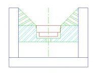
1st thing to consider is the blending of the radius on the tweeters integral waveguide and the linear waveguide that it is installed into occurs only for a few degrees of the perimeter of the tweeter.
I measured and redrew the tweeters built in waveguide and dome.(first picture)
If it was an interface that existed all the way around the tweeter that would not be good at all.
I need to try and visualize just how many degrees of arc the tweeters integral waveguide and any wave guide that it is inserted into actually interact.
.
I think some mockup and measuring using REW and Virtins virtual instrument package (for THD) is in order.
This is what the built in waveguide and dome on the ND16fe look like.(first Pic)
Maybe moving the tweeter up a little would help.
Of course the square edges at the top would have to be rounded over.
I just do not have a handle on what I want to do here yet.
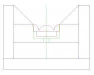
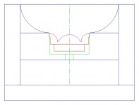
I have been reading allot of threads on tweeter waveguides and wonder if something like the second picture may be closer to what I want.
.
Then again, maybe mounting on a flat baffle would perform just fine.
Either way the flat board with the mounting holes would be required for either setup.
So I guess building that panel is my first step.
Thanks,
Dave
ND16fe.jpg
ND16.jpg
1st thing to consider is the blending of the radius on the tweeters integral waveguide and the linear waveguide that it is installed into occurs only for a few degrees of the perimeter of the tweeter.
I measured and redrew the tweeters built in waveguide and dome.(first picture)
If it was an interface that existed all the way around the tweeter that would not be good at all.
I need to try and visualize just how many degrees of arc the tweeters integral waveguide and any wave guide that it is inserted into actually interact.
.
I think some mockup and measuring using REW and Virtins virtual instrument package (for THD) is in order.
This is what the built in waveguide and dome on the ND16fe look like.(first Pic)
Maybe moving the tweeter up a little would help.
Of course the square edges at the top would have to be rounded over.
I just do not have a handle on what I want to do here yet.
I have been reading allot of threads on tweeter waveguides and wonder if something like the second picture may be closer to what I want.
.
Then again, maybe mounting on a flat baffle would perform just fine.
Either way the flat board with the mounting holes would be required for either setup.
So I guess building that panel is my first step.
Thanks,
Dave
ND16fe.jpg
ND16.jpg
Attachments
Last edited:
Whatever you do, DON'T do the second pic. The parabolic shape focuses the tweeter energy to a point forward of the tweeter. That will create some seriously crazy comb filtering and you'll probably end up with a tweeter that has ragged output from 5khz and above.
If you want to try something quick and dirty, you might consider halving some PVC pipe and aligning it next to your waveguide.
Clay is very helpful for things like this; you can create an ideal shape without wasting a lot of time with sandpaper and bondo.
If you want to try something quick and dirty, you might consider halving some PVC pipe and aligning it next to your waveguide.
Clay is very helpful for things like this; you can create an ideal shape without wasting a lot of time with sandpaper and bondo.
Agree with Patrick on the second one... thus far no one has managed to make a reverse curve work in a beneficial way.
On the first drawing, it would be useful to "cut in" your expansion about 1/2 way along the tweeter's curve, expand from there, not after the full radius shown for the tweeter in the drawing. That creates a nasty discontinuity and will likely mess up the response in the higher freqs...
Otoh, if you use enough of them in parallel, none of this is likely to be required, since you can just EQ the array given that the max SPL in the home is likely to be modest compared to a PA/SR system... each of the tweeters is working at a fraction of the full power and full SPL...
_-_-
The reverse curve is not beneficial for home stereo, but very beneficial for long throw applications.Agree with Patrick on the second one... thus far no one has managed to make a reverse curve work in a beneficial way.
Curt Graber's Hyperspike products use a hyperboloid curve, his HS 60 set the Guinness World Record for the loudest electro-acoustic speaker at 140.2 dB at 128 meters in March of 1997.
I have done a combination using a hyperboloid expansion with a line array:
HyperboLine ™ new Player in the Old Game
It was very beneficial for projection over long distance.
That said, Shadydave's tweeters will be better off without messing with horn loading or an extended waveguide, that stuff needs to be done nicely from the inside out, not tagged on
") .
.Art

SNIP...
That said, Shadydave's tweeters will be better off without messing with horn loading or an extended waveguide, that stuff needs to be done nicely from the inside out, not tagged on
Art
SNIP....
I think I am starting to agree that a simple flush mount line, done well (and close) is probably the best option.
.
140dB@128meters!!
Yeah, that is what I need, put the array at the neighbors house.
Dave
- Status
- This old topic is closed. If you want to reopen this topic, contact a moderator using the "Report Post" button.
- Home
- Loudspeakers
- Multi-Way
- Linear waveguide for Line Array tweets