Hello Marco,
The woofer is a Audax PR330M0. Cast is 33 cm so it's a little bigger than a 30 cm. I can give link to the doc, here : http://www.haut-parleurs.fr/fiches/audax/pr330m0b.jpg
It satisfies me well in 75 l BR, tuned to 31 Hz or so.
The horns are Guigue C300 model. I own those since year 2000. They are wood internal sanded and weight so much ... about 25 kg each") Those are sitting on 3 spikes on the bass unit. So "dangerous life" would be quite adequate.
Those are sitting on 3 spikes on the bass unit. So "dangerous life" would be quite adequate.
Those horns are controversial in some people's mind. Whilst they can give a very nice sounding result, and "measure" pretty well, challenge is to find a decent 1' motor to get it fully set_up. It can be quite challenging as it is a 1' throat, but "long course" horn; dims are l x d x h 45 x 45 x 22 cm. Acoustic cut-off is 220 Hz, which is very low for the horn size ! Sometimes why some people estimate that not possible - or it wouldn't give a nice sound. I measured in my non anechoic environnement about 260 Hz as the horn cut_off, quite close to Mr Guigue's specs, my setup to blame for relative imprecision at those low frequencies (a measure outdoors without any gating would be better for this estimation).
One good candidate is the Altec 909-8A, it can output plenty clean at 500 Hz on those horns. Mr Guigue modifies the compression drivers to suit his needs. This can be good, but also dissuade a lot of people and lead to scepticism, but one good candidate (the one I have) is the modded B&C DE25 driver. Mr Guigue has his own "secrets", but think about a diaphragm treatment similar to Aquaplas. The diaphragm will be (a little) heavier, not having the same character, and will extend bandwidth to the mediums, whilst loosing a bit of top end. This can be passive corrected afterwards. In hi-fi setup it can be practical, and suit one's needs, when in pro sound they would never do it as the coil would overheat and break ...
Well understood. I simulated your xo and it did ok, I also chose 900Hz@-6dB
I was able to use an frd consortium program to output a .frd (mag+phase) of this low pass bessel 6th order. This can be used afterwards in a simulator like SPW, by renaming .frd to .cible or .target (dunno, depends of the lang used) and it can use the frd shape to model the woofer's response.
Acoustic center can be less recessed as computed, all depends of the phase. To control the relative offset I use the step response of the ARTA sweep. With those slopes it's practical and when you know the compression driver's step nude response, the beginning of each driver can be pretty well predicted. Good for a few mm alignment tries.
As I said I think 2nd order Butt on the compression driver seems difficult to obtain in real life in terms of phase exactness relative to theoretical planned one. So offset would be changed to get better phase response maybe ...
And yes; when I passive xo 4th order tuned to get my (actual) 700@-6dB, the shape of the spl target looks like a quasi perfect Bessel_18 in ARTA ... been -6dB@700Hz, means -3 dB is about 975 Hz or so ( Bessel convention = N order related to 45° phase shift); this is why I thought using a Linkwitz 24 on the woofer, being -6dB@700 Hz, with an offset of about 150mm; said a Jimbee model of another quasi_optimal crossover.
The only thing less practical is the geometric offset, shorter than yours. Otherwise, the Bessel_18 and the Link24 are easily obtained, the woofer by simulator, and matches real life; for the horn, you're right, only an electrical 2nd order is needed, and (much more easily) tuned by hand.
Seems we're in the same game sounds VERY interesting
Best,
nAr
OK, thanks to him then!
My system consists of a Fostex FW405N 15" woofer in a damped 180L bass reflex box + Fostex D1400 1" AlNiCo compression driver & Fostex H400 maple radial horn (Fc = 455 Hz) + Fostex T925A AlNiCo horn tweeter (pic attached).
Very true!
That looks like a nice system too! Care to elaborate a bit? Woofer? Compression driver? Nice Guigue-style horn!
The woofer is a Audax PR330M0. Cast is 33 cm so it's a little bigger than a 30 cm. I can give link to the doc, here : http://www.haut-parleurs.fr/fiches/audax/pr330m0b.jpg
It satisfies me well in 75 l BR, tuned to 31 Hz or so.
The horns are Guigue C300 model. I own those since year 2000. They are wood internal sanded and weight so much ... about 25 kg each
Those are sitting on 3 spikes on the bass unit. So "dangerous life" would be quite adequate.Those horns are controversial in some people's mind. Whilst they can give a very nice sounding result, and "measure" pretty well, challenge is to find a decent 1' motor to get it fully set_up. It can be quite challenging as it is a 1' throat, but "long course" horn; dims are l x d x h 45 x 45 x 22 cm. Acoustic cut-off is 220 Hz, which is very low for the horn size ! Sometimes why some people estimate that not possible - or it wouldn't give a nice sound. I measured in my non anechoic environnement about 260 Hz as the horn cut_off, quite close to Mr Guigue's specs, my setup to blame for relative imprecision at those low frequencies (a measure outdoors without any gating would be better for this estimation).
One good candidate is the Altec 909-8A, it can output plenty clean at 500 Hz on those horns. Mr Guigue modifies the compression drivers to suit his needs. This can be good, but also dissuade a lot of people and lead to scepticism, but one good candidate (the one I have) is the modded B&C DE25 driver. Mr Guigue has his own "secrets", but think about a diaphragm treatment similar to Aquaplas. The diaphragm will be (a little) heavier, not having the same character, and will extend bandwidth to the mediums, whilst loosing a bit of top end. This can be passive corrected afterwards. In hi-fi setup it can be practical, and suit one's needs, when in pro sound they would never do it as the coil would overheat and break ...
marco_gea said:The search for a more "comfortable" offset is what drove me to the crossover configuration that I ended up adopting. I get 240 mm with a 900Hz crossover (~0.635*c/Fx).
Well understood. I simulated your xo and it did ok, I also chose 900Hz@-6dB
I was able to use an frd consortium program to output a .frd (mag+phase) of this low pass bessel 6th order. This can be used afterwards in a simulator like SPW, by renaming .frd to .cible or .target (dunno, depends of the lang used) and it can use the frd shape to model the woofer's response.
Acoustic center can be less recessed as computed, all depends of the phase. To control the relative offset I use the step response of the ARTA sweep. With those slopes it's practical and when you know the compression driver's step nude response, the beginning of each driver can be pretty well predicted. Good for a few mm alignment tries.
As I said I think 2nd order Butt on the compression driver seems difficult to obtain in real life in terms of phase exactness relative to theoretical planned one. So offset would be changed to get better phase response maybe ...
And yes; when I passive xo 4th order tuned to get my (actual) 700@-6dB, the shape of the spl target looks like a quasi perfect Bessel_18 in ARTA ... been -6dB@700Hz, means -3 dB is about 975 Hz or so ( Bessel convention = N order related to 45° phase shift); this is why I thought using a Linkwitz 24 on the woofer, being -6dB@700 Hz, with an offset of about 150mm; said a Jimbee model of another quasi_optimal crossover.
The only thing less practical is the geometric offset, shorter than yours. Otherwise, the Bessel_18 and the Link24 are easily obtained, the woofer by simulator, and matches real life; for the horn, you're right, only an electrical 2nd order is needed, and (much more easily) tuned by hand.
marco_gea said:You are NOT wrong at all. This has been exactly what I have measured, and your explanation makes perfect sense. That's also part of the reason why I settled for a quasi-3rd order acoustical high pass on the compression driver (transitioning to 4th order below Fc). The electrical filter to get there is 2nd order.
Cheers!
Marco
Seems we're in the same game
sounds VERY interesting Best,
nAr
Let me ask the stupid question: Have you been able to derive models and parameters for these "cut-offs"?
No stupid question, only "thirsty to learn" spirits here
and with horns if you don't want to fail you need to measure what happens in real life, if you can't output a complex scientific background with a lot of strong mathematical theory.
One can measure the compression alone without a horn, it will exhibit a particular cut-off and phase shift;
same for the horn, with a compression mounted on it will also exhibit its own acoustic cut-off and phase shift (much lower than the compression driver, if well chosen); it will alter the character of the compression driver alone, in terms of frequency, phase response and directivity pattern, relying on the horn character.
Be sure the horn chosen as an effective cut-off well below the driver's one.
This is why it's often said that in real life acoustic designed cut-off for crossover must preferably be greater than 2x horn fc. The compression driver also has to be able to sustain sufficient output at crossover target alone, before using the XO.
Best,
nAr
Hello,
One maybe other interesting target to get large offset would be matching LR6 low pass and LR4 high pass. Phase match is so so , curves cross at -4,6 dB, but group delay is rather constant and axis response is in 0 dB / -0,4 db:
Low pass : LR6 at Fx * 1,07
High pass : LR4 at Fx * 0,92 , -phi, delay : 0,465 c/ fx
crd
An externally hosted image should be here but it was not working when we last tested it.
Thanks for that one Jimbee
The attachment did not pass ...
I wouldn't want to be rude, but I think 3rd order on the high pass would be most desirable, with passive xo ...
with active Xover and 2 amplifiers, the 4th order on the high pass may work better down there.
So any 6th order LP that could match a 3rd order LP in order to get the "quasi-optimal" label could be desirable
One reason is the LPAD using 2 resistors acts as a level shifting impedance bridge,
thus the need for higher components values when placed before LPAD (inductors and capacitors) to "open" down to the medium,
in order to get proper acoustic target.
Any XO calculated with "stock values" on an online calculator,
taking for example 8 ohms as a base for computing will suffer from much less level than desired at crossover point when used with LPAD, compression driver and horn,
and the phase @ XO target will also be different.
Sometimes getting desired target @ XO point needs manual fine tweaking of the components values on the horn electrical section.
Incidentally, it can sum pretty hard with the low pass section crossover, giving dips (often not desirable) in the resulting overall impedance curve.
Using a Butterworth_24 passive on the LP and the hand tweaked 4th order Linkwitz on the HP gives a fairly low impedance at sum, where the 2 lines meet for quite a long time :

- in red, LP Butt_24@700Hz (includes speaker, Zobel, and XO components)
- in blue, HP Link_24@700Hz (includes speaker, LPAD, and XO components tuned to get -6dB@700)
- in black, resulting electrically summed response and phase ( seen by the amplifier )
I can also try to match a LP Link_24 with the actual horn section (acoustical Bessel_18), perhaps slightly different offset to find,
but impedance curve of the LP will be more regular and go up sooner in the frequency domain,
leaving an overall nicer impedance curve :

Best,
nAr
The attachment did not pass ...
I wouldn't want to be rude, but I think 3rd order on the high pass would be most desirable, with passive xo ...
with active Xover and 2 amplifiers, the 4th order on the high pass may work better down there.
So any 6th order LP that could match a 3rd order LP in order to get the "quasi-optimal" label could be desirable
One reason is the LPAD using 2 resistors acts as a level shifting impedance bridge,
thus the need for higher components values when placed before LPAD (inductors and capacitors) to "open" down to the medium,
in order to get proper acoustic target.
Any XO calculated with "stock values" on an online calculator,
taking for example 8 ohms as a base for computing will suffer from much less level than desired at crossover point when used with LPAD, compression driver and horn,
and the phase @ XO target will also be different.
Sometimes getting desired target @ XO point needs manual fine tweaking of the components values on the horn electrical section.
Incidentally, it can sum pretty hard with the low pass section crossover, giving dips (often not desirable) in the resulting overall impedance curve.
Using a Butterworth_24 passive on the LP and the hand tweaked 4th order Linkwitz on the HP gives a fairly low impedance at sum, where the 2 lines meet for quite a long time :

- in red, LP Butt_24@700Hz (includes speaker, Zobel, and XO components)
- in blue, HP Link_24@700Hz (includes speaker, LPAD, and XO components tuned to get -6dB@700)
- in black, resulting electrically summed response and phase ( seen by the amplifier )
I can also try to match a LP Link_24 with the actual horn section (acoustical Bessel_18), perhaps slightly different offset to find
, but impedance curve of the LP will be more regular and go up sooner in the frequency domain,
leaving an overall nicer impedance curve :

Best,
nAr
Last edited:
Hello nAr,
"I wouldn't want to be rude, but I think 3rd order on the high pass would be most desirable, with passive xo ... "
If you want a 6-3 there is a way near Marco's formula :
Low pass : LR6 at Fx * 1,06
High pass : Butt 3 at Fx * 1,13 , -phi , delay = 0,445 c/Fx
good axis response ( + 0,3 - 0,3 dB ), curves cross at -4,6dB :
crd
An externally hosted image should be here but it was not working when we last tested it.
Hello nAr,
If you want a 6-3 there is a way near Marco's formula :
Low pass : LR6 at Fx * 1,06
High pass : Butt 3 at Fx * 1,13 , -phi , delay = 0,445 c/Fx
good axis response ( + 0,3 - 0,3 dB ), curves cross at -4,6dB :
Thank you Jimbee!
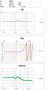
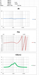
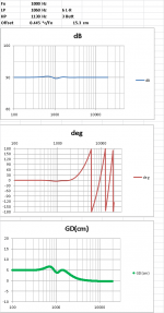
So, to recapitulate, here are the simulations of three of the crossovers discussed in this thread:
(1) JMLC's original Butt 3 + Butt 3
(2) My TAD-derived LR 6 + Butt 3
(3) Jimbee's tweaked LR 6 + Butt 3
It seems as if (1) and (3) present the smoothest phase and GD curves, with (3) affording a double offset vs (1); (2) gets one the most offset, but at the cost of a relatively bumbier phase and GD...
Attachments
Thank you Jimbee!
So, to recapitulate, here are the simulations of three of the crossovers discussed in this thread:
(1) JMLC's original Butt 3 + Butt 3
(2) My TAD-derived LR 6 + Butt 3
(3) Jimbee's tweaked LR 6 + Butt 3
It seems as if (1) and (3) present the smoothest phase and GD curves, with (3) affording a double offset vs (1); (2) gets one the most offset, but at the cost of a relatively bumbier phase and GD...
...and (4) Jimbee's LR 6 + LR 4:
as good as (in fact, slightly better than) (3), and with a slightly larger offset - bravo!
Marco
Attachments
jmbee - Your latest filters looks like what I was looking for: offset length between the TAD and JMLC filters; well-behaved group delay; and filter orders that the drivers should work well with. It looks like a good starting point for testing.
Marco and nAr - Your hands-on experience and the side-by-side comparison of the filters are most useful - and a source of inspiration.
A question: Is anybody using Spice for their simulations? I'm entertaining the idea of simulating the effect of the driver and horn after the crossover. I have Marshall Leach's papers and files (basic simulations and his paper on simulation of the Salmon's family of horns.) Such simulation must have been done already by someone...
Another question: Is there a Spice model of the JMLC horn's profile available?
Many thanks
Pierre
jmbee - Your latest filters looks like what I was looking for: offset length between the TAD and JMLC filters; well-behaved group delay; and filter orders that the drivers should work well with. It looks like a good starting point for testing.
Marco and nAr - Your hands-on experience and the side-by-side comparison of the filters are most useful - and a source of inspiration.
A question: Is anybody using Spice for their simulations? I'm entertaining the idea of simulating the effect of the driver and horn after the crossover. I have Marshall Leach's papers and files (basic simulations and his paper on simulation of the Salmon's family of horns.) Such simulation must have been done already by someone...
I don't, but I use SPW with .zma and nude .frd for simulating real life response vs targets. It is quite predictible on the direct radiation speakers, for SPL target but phase in real life (not minimal) will be different; with the horns it can sometimes differ for SPL result in the low part of the medium curve. Phase prediction is quite precise, but not absolute.
I have seen some people using Spice and they seem to quite like it. So go for it
Another question: Is there a Spice model of the JMLC horn's profile available?
Many thanks
Pierre
It should exist. Maybe jmmlc will help ...
Best
I'll second that.I wonder if reading this Thread three times will get me close to fully understanding the topic?
Keep going I'm all ears.
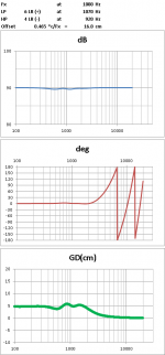
UPDATE: real measured results
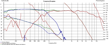
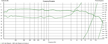
...Finally, here's the measured response of my newly realized filter of this kind (Woofer LP 36dB/oct LR + Horn HP 24 dB/oct LR à la Jimbee), with Fx = 900Hz (as you can see, the horn is also low-passed at 7kHz, as in my case a Tweeter then takes on the last 1.5 octaves after that).
Please note the excellent ensuing linearity of the overall (Woofer+Mid) phase response till almost 3 kHz (second attachment): indeed, a "quasi-optimal" result!
Kind regards,
...and (4) Jimbee's LR 6 + LR 4:
as good as (in fact, slightly better than) (3), and with a slightly larger offset - bravo!
Marco
...Finally, here's the measured response of my newly realized filter of this kind (Woofer LP 36dB/oct LR + Horn HP 24 dB/oct LR à la Jimbee
), with Fx = 900Hz (as you can see, the horn is also low-passed at 7kHz, as in my case a Tweeter then takes on the last 1.5 octaves after that).Please note the excellent ensuing linearity of the overall (Woofer+Mid) phase response till almost 3 kHz (second attachment): indeed, a "quasi-optimal" result!
Kind regards,
Attachments
Slightly different context, but probably worthwile to mention here :
http://www.diyaudio.com/forums/mult...-using-excess-group-delay-10.html#post2970292
The idea there was to design like no offset were present but then add a correction lowpass that delays the woofer (and filters it higer up, too) as needed, slightly adjusting some XO params in the process to get the best phase fit and amplitude flatness.
...Finally, here's the measured response of my newly realized filter of this kind
Wow ! This just confirmed this is a filter I want to try. Many thanks!
How does it sound?
Well, it sounds real good to me (But then, "beauty is in the eye of the beholder" - or the listener in this case, isn't it? ;-))
...more seriously: it does seem to me to produce a commendable cohesiveness in the sound across the whole frequency spectrum (in fact, rather impressively so, given the visual discontinuity between the large 15" woofer and the relatively small 1" horn). It also gives a very focused virtual image, not unlike that of a good full-range driver.
In the end, I think those who still think that systems like these (large woofer + horn) inevitably force you to renounce coherence and imaging for the sake of sheer dynamics, should do themselves a favour and give one of these "quasi-optimal" crossovers a go!
Marco
(But then, "beauty is in the eye of the beholder" - or the listener in this case, isn't it? ;-))...more seriously: it does seem to me to produce a commendable cohesiveness in the sound across the whole frequency spectrum (in fact, rather impressively so, given the visual discontinuity between the large 15" woofer and the relatively small 1" horn). It also gives a very focused virtual image, not unlike that of a good full-range driver.
In the end, I think those who still think that systems like these (large woofer + horn) inevitably force you to renounce coherence and imaging for the sake of sheer dynamics, should do themselves a favour and give one of these "quasi-optimal" crossovers a go!
Marco
To recapitulate
For the record, here's a list of "approved" “quasi-optimal” crossovers in order of increasing offset:
3rd order Butterworth Low Pass, -3dB @ Fx*0.87 (+)
3rd order Butterworth High Pass, -3dB @ Fx*1.15 (-)
Offset = 0.22*c/Fx
4th order L-R Low Pass, -6dB @ Fx (+)
3rd order Bessel High Pass, -3dB @ Fx*1.4 (-)
Offset = 0.29*c/Fx
4th order L-R Low Pass, -6dB @ Fx (+)
4th order L-R High Pass, -6dB @ Fx (-)
Offset = 0.31*c/Fx
6th order Bessel Low Pass, -6dB @ Fx*1.25 (+)
2nd order Butterworth High Pass, -3dB @ Fx*1.3 (-)
Offset = 0.40*c/Fx
6th order L-R Low Pass, -6dB @ Fx * 1.06 (+)
3rd order Butterworth High Pass, -3dB @ Fx* 1,13 (-)
Offset = 0.445 c/Fx
6th order L-R Low Pass, -6dB @ Fx * 1.07 (+)
4th order L-R High Pass, -6dB @ Fx * 0.92 (-)
Offset = 0.465 c/Fx
Marco
For the record, here's a list of "approved"
“quasi-optimal” crossovers in order of increasing offset:3rd order Butterworth Low Pass, -3dB @ Fx*0.87 (+)
3rd order Butterworth High Pass, -3dB @ Fx*1.15 (-)
Offset = 0.22*c/Fx
4th order L-R Low Pass, -6dB @ Fx (+)
3rd order Bessel High Pass, -3dB @ Fx*1.4 (-)
Offset = 0.29*c/Fx
4th order L-R Low Pass, -6dB @ Fx (+)
4th order L-R High Pass, -6dB @ Fx (-)
Offset = 0.31*c/Fx
6th order Bessel Low Pass, -6dB @ Fx*1.25 (+)
2nd order Butterworth High Pass, -3dB @ Fx*1.3 (-)
Offset = 0.40*c/Fx
6th order L-R Low Pass, -6dB @ Fx * 1.06 (+)
3rd order Butterworth High Pass, -3dB @ Fx* 1,13 (-)
Offset = 0.445 c/Fx
6th order L-R Low Pass, -6dB @ Fx * 1.07 (+)
4th order L-R High Pass, -6dB @ Fx * 0.92 (-)
Offset = 0.465 c/Fx
Marco
- Status
- This old topic is closed. If you want to reopen this topic, contact a moderator using the "Report Post" button.
- Home
- Loudspeakers
- Multi-Way
- "Quasi-optimal" crossover for high-efficiency loudspeaker system