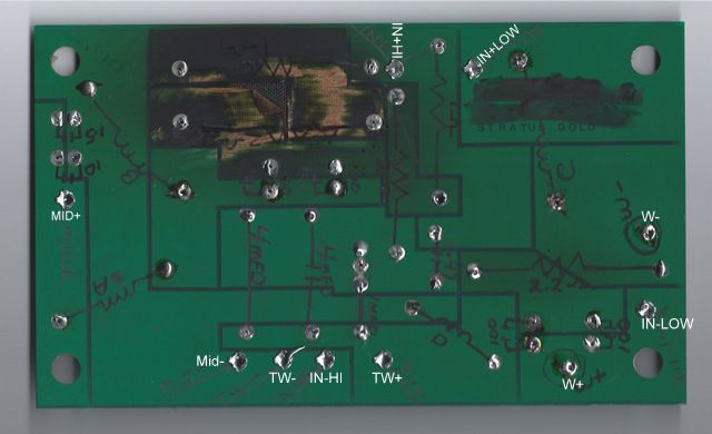
Hello all. I need to rebuild the x-over on my beloved Golds after I fried the x-over board, I mean burnt by an overheated resistor to the point I can't follow the board traces to get the schematics! I have called PSB and they would only give me the values of the resistors, but no schematics. Can anyone steer me in the right direction??? I will rebuild them one way or another and will post the outcome.
Did you talk to customer service in Toronto? (Not Boston, engineering is in Toronto) They should have been more helpful than that. If they don't have a drawing, ask if they could just put a PC board on the photocopier or fax/e-mail you a schematic.
Lenbrook Canada
633 Granite Court
Pickering, Ontario, Canada L1W 3K1
Phone: (905) 831-6555
Fax: (905) 831-6936
Alternatively, trace out what you do have and attach a picture to the thread. I'll bet we can figure out the missing traces based on what makes the circuit sensible.
David S.
Lenbrook Canada
633 Granite Court
Pickering, Ontario, Canada L1W 3K1
Phone: (905) 831-6555
Fax: (905) 831-6936
Alternatively, trace out what you do have and attach a picture to the thread. I'll bet we can figure out the missing traces based on what makes the circuit sensible.
David S.
Sorry it has taken so long to get back. I have figured out the burnt board and have made up a schematic of the circuit.
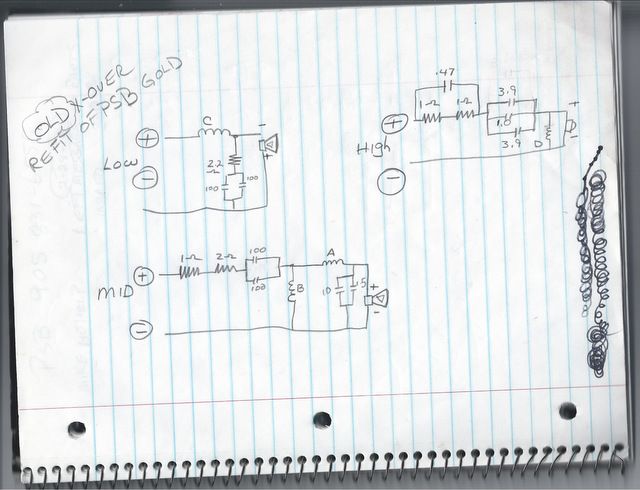
Now I have some questions. Is the translation right from the board to the drawing? The resistors on the midrange are the ones that burnt, the caps didn't look too good either. Why did they get so hot? I have played them loud before with no problems. I'm driving them with a McCormack DNA-1 Special Edition. One more question. I plan on rebuilding the x-over with better quality parts, should I stick with the circuit as is or try to improve on it?
Now I have some questions. Is the translation right from the board to the drawing? The resistors on the midrange are the ones that burnt, the caps didn't look too good either. Why did they get so hot? I have played them loud before with no problems. I'm driving them with a McCormack DNA-1 Special Edition. One more question. I plan on rebuilding the x-over with better quality parts, should I stick with the circuit as is or try to improve on it?
It is my day for threads matching my background. I reverse engineered the PSB Stratus Gold years ago and your schematic looks correct from memory. The two 100 uFs feeding the mid looks high but I'm probably just not remembering correctly - you might want to check them.
Check if the midrange is somehow shorted, perhaps due to overheating.
Might as well check all the drivers, just to be sure.
You do not want to change anything but to replace the old electrolytics and damaged resistors - that is an excellent design.
Check if the midrange is somehow shorted, perhaps due to overheating.
Might as well check all the drivers, just to be sure.
You do not want to change anything but to replace the old electrolytics and damaged resistors - that is an excellent design.
Yes the 100uFs are correct. Are you planning to replace electrolytics with the same type?
The shunt on the mid is 10uF in parallel with 5 uF is that correct? I seem to remember when I simulated that a nearly ideal cap, such as a film type with low ESR, had some peaking at the high end of the low pass about .5 ohm added in series to simulate the actual ESR fixed it. You should add a small resistor there if you change to film.
I don't usually use bypass caps.
I think you said that the 100uFs on the mid looked damaged or overheated. My guess is that they lost form which causes the breakdown voltage to drop, then when high power (voltage) is applied they break down further and heat up until they shorted causing the high power in the bass to drive the input Rs since the shunt inductor has low Z at LF.
Did both channels fail?
Did both channels fail?
Electrolytic caps need voltage applied to keep the plates "formed" with the proper oxide layer. Based on this it is surprising that electrolytic caps work in speakers where they sit for long periods of time with no voltage applied, but probably modern caps have gotten better and work fine until they age. The best way to reform them is to slowly increase the applied voltage but this is generally impractical. I suppose if your speakers have sat for months or played only at low listening levels, you might give them a day of moderate level or slowly increased level before driving them real hard. On the other hand, if the caps are at end of life there might not be any hope for them. It is interesting that this is the first report I've seen of such a failure.
I've seen a few others of "blown" up caps in speakers but not in exactly the same way.
Film caps do not rely on an oxide layer and have no "form" effect at all.
The tweeter circuit in the PSBs uses all film caps, as I recall, so you should not have to change them.
They were box shaped in mine with I think 100V rating or so.
Last edited:
That is a 1.5mF with the10mF as the shunt. I will be hard wiring the new x-over and I will be sure to give them plenty of space, maybe even heat sinks. So much info so fast I need to take notes!
Ha, I remembered about 12 uF there so that makes sense!
Are they both electrolytics? The smaller one would be the shunt.
I don't remember two caps there on mine but it was a long time ago.
Just figured you had it right in front of you so I was not remembering correctly.
Capacitors and inductors do not consume power in theory, meaning they don't get hot. Their design in practice is imperfect but still, they'd normally fail due to running them beyond their specs or in the case of electrolytics it is because they become unreliable with age.I will be sure to give them plenty of space, maybe even heat sinks. So much info so fast I need to take notes!
Resistors do get hot. Feel free to use units designed to handle some power. Mount them where they can get some air flowing around them without passing it too directly on to another component. Try not to make the legs too short, and ensure these resistors are supported so they don't snap off unexpectedly when subjected to vibration.
I think I am missing something here. The 10 and 1.5mF caps are parallel, so that = 11.5mF right.
They are working together, both electrolytic. They are wired across the + and- on the midrange. Is this what is called a shunt? I don't want to bypass these since they are not in the signal path. I do want to bypass the 2 100mF caps that are feeding the mid circuit. What size should I use? Does it matter? Pete, should I use that 0.5 ohm here, in series with the film bypass cap? I'm only going to heatsink the resistors.
They are working together, both electrolytic. They are wired across the + and- on the midrange. Is this what is called a shunt? I don't want to bypass these since they are not in the signal path. I do want to bypass the 2 100mF caps that are feeding the mid circuit. What size should I use? Does it matter? Pete, should I use that 0.5 ohm here, in series with the film bypass cap? I'm only going to heatsink the resistors.
The Stratus Gold was supposedly built to tight standards, not sure how they did it,
perhaps the caps were selected for tight tolerance. David do you know any details about this?
I'd use a pair of poly film caps of 1% value that total 11.5 uF (4.7 + 6.8) with .33 ohms
in series. These are the only 1% types I know of:
Dayton Audio PMPC-4.7 4.7uF 250V Precision Audio Capacitor 027-230
http://www.parts-express.com/pe/showdetl.cfm?partnumber=027-238
Or 3%:
4.7uf, 250V
6.8uf, 250V
There is no reason to bypass high quality film caps.
I would not add a bypass to the 100uFs they were not in the original design
and are not needed. I'd use good quality electrolytics since films this large
are so expensive and to keep it as designed. I'd use Bennic NPEs and nothing
of lesser quality:
The Madisound Speaker Store
I've been thinking that my Stratus Golds need recapping so you made me think
about how to do it.
Last edited:
- Home
- Loudspeakers
- Multi-Way
- PSB Stratus gold X-over help