I brought this back up to make it easier to explain for me. The 10 and 1.5mF caps across the midrange were electrolytics on the original board. Should I change them to film type caps? I hope I'm not sounding dumb here, I just want to get it right. You have helped me out and I appreciate your involvement.
Great! Now there will be two of us rebuilding Gold x-overs. The more the merrier.
The Stratus Gold was supposedly built to tight standards, not sure how they did it,
perhaps the caps were selected for tight tolerance. David do you know any details about this?
The Gold was still in production when I arrived at PSB, but I didn't have any involvement in it. I don't recall any particular special production methods (i.e. parts sorting) but good quality parts would be used.
Is anybody actually measuring the ESR of low ESR electrolytics? I've found it to be pretty inconsequential in the past. I do remember some high ESR (standard, rather than low) that had enough resistance to lower the tweeter curve a bit, but nothing of importance from good electrolytics.
The network drawings look good to me and follow a topology that Paul Barton would tend to use.
Regards,
David
I brought this back up to make it easier to explain for me. The 10 and 1.5mF caps across the midrange were electrolytics on the original board. Should I change them to film type caps? I hope I'm not sounding dumb here, I just want to get it right. You have helped me out and I appreciate your involvement.
Great! Now there will be two of us rebuilding Gold x-overs. The more the merrier.
If you want to play it safe keep them as NPEs.
I am going to change them to film types such as the ones I linked to with .33 ohms in series.
I would not change the larger 100 uF caps.
I have measured the ESR of electrolytics and it varies with frequency but is usually around .1 to .5 ohms. I've measured some as high as 1.2 ohms. It depends on the DF spec of the cap; common values are 5 and 10% lower being better.
If you are wondering about those caps in parallel, what I think PSB does is to buy large quantities
of common values such as 100, 10, 1 uF then put them in parallel to get what they need. I don't
believe that there is any "magic" bypassing going on with any of them.
Last edited:
I seem to recall that the combination of the positions of the woofer and mid, and the crossover frequency and overlap were set up to stagger the floor bounce frequencies of the woofer and mid. Mid over tweeter probably tilts the main crossover lobe up, rather than down so that the system sounds good standing.
The Stratus Gold is an excellent design.
The Stratus Gold is an excellent design.
Crossover layout
I was just going over how I am going to wire the new x-over and I remembered reading somewhere to avoid common return paths. Any thoughts on this? Also, just wondering. What is the make and model of the woofer in the Stratus Gold. The mid and tweeter are clearly tagged VIFA. Tony
I was just going over how I am going to wire the new x-over and I remembered reading somewhere to avoid common return paths. Any thoughts on this? Also, just wondering. What is the make and model of the woofer in the Stratus Gold. The mid and tweeter are clearly tagged VIFA. Tony
I'd wire it the same way as it was from the factory, unless you've
found a problem.
The woofer is custom, I've talked to Paul Barton about it.
Are you able to measure the free air resonance?
The mid is custom, very similar to the popular P17 but with a smaller 1"
voice coil. The more common version with the 32mm voice coil is back in
production under Scan Speak:
http://www.madisoundspeakerstore.com/scanspeak-woofers-6-7/scanspeak-classic-p17wj00-6.5-woofer/
The tweeter has a custom faceplate but otherwise looks like the old D25AG
without the rear chamber.
Last edited:
No problem really, just that it was wired for bi-amping or separate speaker wire inputs. I don't like to use jumpers. But on second thought, I am restoring them so I might as well restore them 100%. That is except for the addition of the 1% caps in the x-over. All I have for test equipment is a Radio Shack SPL meter and a signal generator. Can I do it with that??
I once had an RS meter (the older one) with a line out socket on the side so it went straight to the computer. You'll want to get a feel for the response of the mic, there are a few examples around and there are some mods you can do to extend the bandwidth. You could use the signal generator to make rudimentary impedance measurements with a volt meter, but you can use your computer for that as well.
If you want to play it safe keep them as NPEs.
I am going to change them to film types such as the ones I linked to with .33 ohms in series.
I would not change the larger 100 uF caps.
I meant to say, or to be more clear:
I would not change the larger 100 uF caps to film types.
Not sure if that was clear, certainly replace all the NPEs.
Pete, you were clear the first time. Thanks for checking.
AllenB. The one I have is an older one with the output on the side. I have been looking around for software that would test for T/S parameters and an LCR meter. Any ideas?
Keep it reasonable, please.
What program is everyone using to sim. x-overs?? That looks interesting. Tony
AllenB. The one I have is an older one with the output on the side. I have been looking around for software that would test for T/S parameters and an LCR meter. Any ideas?
Keep it reasonable, please.
What program is everyone using to sim. x-overs?? That looks interesting. Tony
These aren't the type of thing I use a computer for but I hear Limp, which comes with Arta will take an impedance plot easily enough. Any spectrum analyser could be used that way, and you'll need it for the response measurements. HolmImpulse is easy to use and free.test for T/S parameters and an LCR meter.
Yes Limp should work well, but I have not tried it since I have another older program:
ARTA Home
You have to make some test leads to use it safely that are documented on that site.
I use the very old CALSOD program for crossover/system simulation but many
people use PCD by Jeff B.:
http://audio.claub.net/software/jbabgy/jbagby.html
Many people on the Parts Express forum use it, and Jeff B. is there also:
http://techtalk.parts-express.com/forumdisplay.php?2-Tech-Talk-Forum
Last edited:
Pete, did you up grade your caps yet? Did you make a schematic of the board and values? I would like to double check mine against yours before I start to solder it all together. Tony
Hi Tony, I won't be getting around to doing mine for some time but I did
find my notes from 1996 where I traced out the circuit and read the values
off of the components on the circuit board. I also measured the inductors
and most of the components.
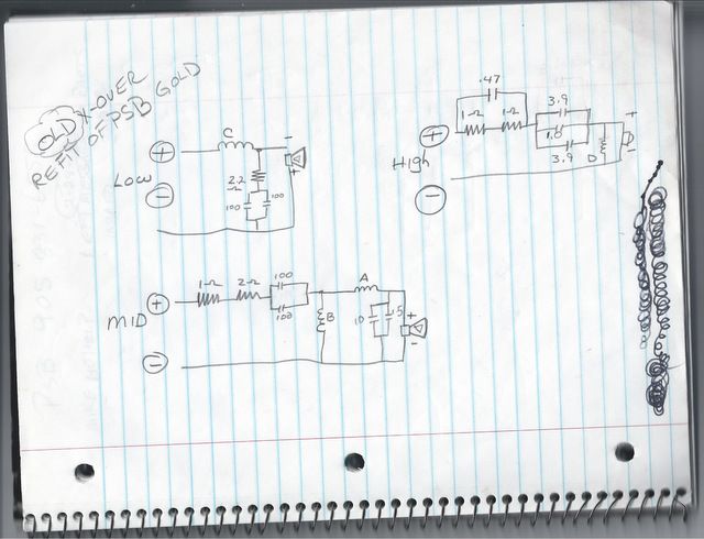
Tweeter D25AG-07:
Series resistors were 1.8R/10W
But it also had an 18R/5W in parallel with the pair
Total measured 3.0 ohms as would be expected from the total calculated value.
.47 uF cap in parallel
Series cap was two 4uF 10% 200V MKC Film caps in parallel
I show a trim, but I could not read the value
Total capacitance measured 8.2 uF at 1 KHz
The shunt inductor measured .15 mH/.33 ohms
Midrange Vifa P17WH-07:
series resistors were 1.8R/20W and 2.0R/20W
Caps were two 100uF in parallel
Shunt inductor was 1.6 mH .62R
Series inductor was 1.6 mH .9R
Shunt caps were 10 uF and 5 uF 100V but I might have read the 5 wrong since
this showed peaking in simulation that I did not measure in the actual design.
I measured the parallel pair to be 12.1 uF .47R at 1 KHz
The 5 was probably 1.5 uF as you have noted.
Woofer 10" custom:
series 3.3 mH 1.0R
2R 20W to shunt cap
Two 100 uF 50V caps in parallel
Woofer out of phase, all others in phase.
Tweeter caps MKC Film all other caps Intercap 85 deg C 50V NPE
I have cloned it with the standard Vifa D25AG06 tweeter, P17WJ00-08 mid
and various woofers. The Polk Db1240 12" woofer works well. Be sure to
position the drivers in a similar configuration and distance from the floor.
This speaker sounds amazing with deep, extended powerful bass.
Yours looks to be a newer revision with very minor changes. 2 ohms total
on your tweeter, 3 ohms total on mine. 3 ohms total on your mid, 3.8 total
on mine. The rest of the differences are very minor. Yours are voiced a bit
hotter.
find my notes from 1996 where I traced out the circuit and read the values
off of the components on the circuit board. I also measured the inductors
and most of the components.
Tweeter D25AG-07:
Series resistors were 1.8R/10W
But it also had an 18R/5W in parallel with the pair
Total measured 3.0 ohms as would be expected from the total calculated value.
.47 uF cap in parallel
Series cap was two 4uF 10% 200V MKC Film caps in parallel
I show a trim, but I could not read the value
Total capacitance measured 8.2 uF at 1 KHz
The shunt inductor measured .15 mH/.33 ohms
Midrange Vifa P17WH-07:
series resistors were 1.8R/20W and 2.0R/20W
Caps were two 100uF in parallel
Shunt inductor was 1.6 mH .62R
Series inductor was 1.6 mH .9R
Shunt caps were 10 uF and 5 uF 100V but I might have read the 5 wrong since
this showed peaking in simulation that I did not measure in the actual design.
I measured the parallel pair to be 12.1 uF .47R at 1 KHz
The 5 was probably 1.5 uF as you have noted.
Woofer 10" custom:
series 3.3 mH 1.0R
2R 20W to shunt cap
Two 100 uF 50V caps in parallel
Woofer out of phase, all others in phase.
Tweeter caps MKC Film all other caps Intercap 85 deg C 50V NPE
I have cloned it with the standard Vifa D25AG06 tweeter, P17WJ00-08 mid
and various woofers. The Polk Db1240 12" woofer works well. Be sure to
position the drivers in a similar configuration and distance from the floor.
This speaker sounds amazing with deep, extended powerful bass.
Yours looks to be a newer revision with very minor changes. 2 ohms total
on your tweeter, 3 ohms total on mine. 3 ohms total on your mid, 3.8 total
on mine. The rest of the differences are very minor. Yours are voiced a bit
hotter.
Last edited:
- Home
- Loudspeakers
- Multi-Way
- PSB Stratus gold X-over help