Hi
I'm hoping that I can get some help on this.
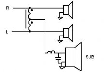
This is a diagram of what i'm wanting to do.
I'm pretty limited on space as this is going to be occupying a desktop as such I would like to have a small box for all of the active stuff and then three separate boxes. 1 stereo set of 3" tang bamboo full range drivers and 1 woofer that can carry the low end of each stereo channel.
Is it possible to do this with one cross-over? I would think doing that I would lose the stereoness and end up with two mono channels.
Anyone have any ideas on how I can take the lower end of each stereo channel into one woofer with a minimal amount of space required?
I'm hoping that I can get some help on this.
This is a diagram of what i'm wanting to do.
An externally hosted image should be here but it was not working when we last tested it.
I'm pretty limited on space as this is going to be occupying a desktop as such I would like to have a small box for all of the active stuff and then three separate boxes. 1 stereo set of 3" tang bamboo full range drivers and 1 woofer that can carry the low end of each stereo channel.
Is it possible to do this with one cross-over? I would think doing that I would lose the stereoness and end up with two mono channels.
Anyone have any ideas on how I can take the lower end of each stereo channel into one woofer with a minimal amount of space required?
yes, it's possible and easy
to join the L+R use 10k resistor or a little bit higher, from here use a low pass active filter
if you want you can make 2 high pass filters for the front speaker too
i'm doing this for my gainclone, if you ned i have the pcb layout for a 2 way high pass filter 24db/oct + a mono exit to plug in the low pass filter
the pcb is pretty small
I think the OP wanted a solution at the speaker level not at the signal level.
See jpg for speaker level power combiner
Signals common to both channels will show up at the sub the same as an active signal (line level) mixer.
Advantages:
no power amp needed
Disadvantages:
(or requirements)
XL of the power combiner transformer (centre tap transformer) should be high 50ohms???) at the lowest frequency.
The inductor self resonance should be high enough to not become capacitive at frequencies that the R & L amps are generating.
The inductor should be able to (without saturating) withstand any difference in R vs L amplifier output. (stereo signals)
Has to handle the power you are going to put through it.
This is probably why this technique is used at RF frequencies and not AF.
Easier to build/buy an amplifier.
Hope that helps.
Attachments
Pedro - I would be interested to see the pcb layout and the components needed. You mentioned it was active....what's the power requirement?
Dug - I am interested by this idea but need some more information.
I am using a 25 watt max amp to power 3 x 8 ohm speakers. Two full ranges and one woofer. I want to xover the 2 x 3" full ranges so that they do not have to handle anything too low and use the 8" woofer for the low frequencies.
I assume the transformer in your diagram is an audio level one. What values of the inductors/capacitors and transformer. Or at least what formula should I use?
If you wanted to try without designing/building a transformer:
Use the SECONDARY of a 60Hz power transformer. (leave the primary open...not connected to anything)
At your 25W levels:
for down to 60Hz operation a 40VACct at 5A
for down to 30Hz operation a 80VACct at 5A
for down to 20Hz operation a 120VACct at 5A
I would not expect a 60Hz laminated core power transformer to operate much above a few 100 Hz but some people have stated that toroids operate at higher frequencies.
If you look at the sizes of these transformers you will see why this is not a popular solution.
For the sub low pass filter consult someone more knowledgeable than I.
The inductor for the sub low pass filter might be better placed in the feeds to the transformer to help isolate the R & L channels from each other at non-sub frequencies. The cap can stay where it is.
You might also want to put a fuse in one of the transformer feeds...just in case.")
Have fun and let us know if it works.
Use the SECONDARY of a 60Hz power transformer. (leave the primary open...not connected to anything)
At your 25W levels:
for down to 60Hz operation a 40VACct at 5A
for down to 30Hz operation a 80VACct at 5A
for down to 20Hz operation a 120VACct at 5A
I would not expect a 60Hz laminated core power transformer to operate much above a few 100 Hz but some people have stated that toroids operate at higher frequencies.
If you look at the sizes of these transformers you will see why this is not a popular solution.
For the sub low pass filter consult someone more knowledgeable than I.
The inductor for the sub low pass filter might be better placed in the feeds to the transformer to help isolate the R & L channels from each other at non-sub frequencies. The cap can stay where it is.
You might also want to put a fuse in one of the transformer feeds...just in case.
Have fun and let us know if it works.
What frequency range did you want the sub to handle?
Probably around 30 to 600 hz.
If you wanted to try without designing/building a transformer:
Use the SECONDARY of a 60Hz power transformer. (leave the primary open...not connected to anything)
At your 25W levels:
for down to 60Hz operation a 40VACct at 5A
for down to 30Hz operation a 80VACct at 5A
for down to 20Hz operation a 120VACct at 5A
I would not expect a 60Hz laminated core power transformer to operate much above a few 100 Hz but some people have stated that toroids operate at higher frequencies.
If you look at the sizes of these transformers you will see why this is not a popular solution.
For the sub low pass filter consult someone more knowledgeable than I.
The inductor for the sub low pass filter might be better placed in the feeds to the transformer to help isolate the R & L channels from each other at non-sub frequencies. The cap can stay where it is.
You might also want to put a fuse in one of the transformer feeds...just in case.
Have fun and let us know if it works.
Thanks for the suggestion Dug but the cost and weight of that iron will probably put that in the horizon. Seems like something fun to try some time when the amp driving it is more worth it.
Probably around 30 to 600 hz.
600Hz is to high, cut the sub on a a maximum of 120HZ
do you already have the speakers? What models they are?
When i get home i will post it, i have made the pcb but not assembled and tested, the cut is 70hzPedro - I would be interested to see the pcb layout and the components needed. You mentioned it was active....what's the power requirement?
The board need +-12 or +-15
Dual voice coil sub, 1 coil to each channel.
But if the channels don't have the same signal the sub will be forcing on coil with the other, not a good idea, and most dual coil have a impedance of 2ohms, another problem on how to wire with the main speaker, keep the power distribution and have a impedance>4ohms
if you plug one channel in each coil of the subwoofer one will be forcing mecanically the sub woofer
This is not true. Force is applied on the cone of a loudspeaker as a result of the magnetic field created by current flowing through the voice coil of the loudspeaker interacting with the magnetic field of the loudspeaker's permanent magnet.
In the case of the dual voice coil loudspeaker, the magnetic fields around each voice coil add or subtract depending on the relative polarity and strength of each field. The direction and amount of force exerted on the cone is dependent on the resultant field produced by the two coils. In other words, the pair of magnetic fields corresponding to the two currents in the voice coils add and subtract. There is no tug of war between the voice coils acting on the former attached to the cone.
Dual VC sub driver and use it as a .5
At least that is what I have in our bedroom at the moment, fed through a pair of cheap cored inductors plus extra wire scramble wound on top finished value of ~12mH and a DCR of ~1R5
Even tough some of the low frequencies are going to the L&R the .5 woofer takes a lot of the bass out and cleans up the midbass and midrange reasonably well. Going active is much better, however I needed a cheap option at the time
One way would be a dual voice coil sub-woofer, and a first order series cross-over at each Left/ right speaker outputs of your power amplifier. The big disadvantage here would be very large inductors and many micro-Farad non-polarized capacitors.
Are you building the active electronics? If so, then a second way entailing creating left, right and sub-woofer signal channels with an active cross-over network at line level eliminates the need for the dual voice coil driver and the large inductors/ capacitors. However then you also need three channels of power amplification.
Regards,
Pete
Hi
I'm hoping that I can get some help on this.
This is a diagram of what i'm wanting to do.
An externally hosted image should be here but it was not working when we last tested it.
I'm pretty limited on space as this is going to be occupying a desktop as such I would like to have a small box for all of the active stuff and then three separate boxes. 1 stereo set of 3" tang bamboo full range drivers and 1 woofer that can carry the low end of each stereo channel.
Is it possible to do this with one cross-over? I would think doing that I would lose the stereoness and end up with two mono channels.
Anyone have any ideas on how I can take the lower end of each stereo channel into one woofer with a minimal amount of space required?
I would just use two woofers in the same subwoofer box. One for each channel with a partition separating the two drivers internally. Essentially a dual mono subwoofer. This will make the crossover the easiest. You can still get some acoustic cancellation this way to. But it should be good enough for a computer set up. You can make the box as big as you have room and custom sized to fit in an out of the way place like behind the desk. You can make the box long and slim so the two subwoofer drivers are as far apart as possible.
Another option would just be two small and easy to place subwoofers. One for each channel. I think this would be the best approach. Alowing you to maximize sound quality and open more placement options. Including keeping the subwoofers away from the main computer case to avoid magnetic problems.
Last edited:
- Status
- This old topic is closed. If you want to reopen this topic, contact a moderator using the "Report Post" button.
- Home
- Loudspeakers
- Multi-Way
- Looking to make a mono sub from a stereo output while keeping stereo speakers.