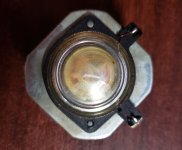
What do you think is the best solution if the tweeter has completly to be changed? In my two pairts of 751 the rectangle version of this peerless 811839 in one item has now been crushed by the dried ferrofluid.
I keep the crosspoint of 2,1 kHz in mind. Looking for tweeters which allow this deep crosspoint i found
Monacor DT-28n
MONACOR - - Produkte - DT-28N
or
G 20 SC - 8 Ohm | Visaton
I am afraid of surprises from the efficiency factor.
Thanks for any help!!
Pit
I keep the crosspoint of 2,1 kHz in mind. Looking for tweeters which allow this deep crosspoint i found
Monacor DT-28n
MONACOR - - Produkte - DT-28N
or
G 20 SC - 8 Ohm | Visaton
I am afraid of surprises from the efficiency factor.
Thanks for any help!!
Pit
Upgraded the filter caps of my 751s with the original values: 4.3uf, 4.7uf and 5.6uf as my old caps sounded a bit veiled and muddy. Dayton has really nice caps made by Solen (Dayton Audio DMP,) which have the exact value and fit right in. I was pleasantly surprised with the result. ") . Ordered ferrofluid for the tweeters, but not sure if I should bother for the moment. Is there a way to know when to replace the fluid?
. Ordered ferrofluid for the tweeters, but not sure if I should bother for the moment. Is there a way to know when to replace the fluid?
. Ordered ferrofluid for the tweeters, but not sure if I should bother for the moment. Is there a way to know when to replace the fluid?Lica, my experience is limited but I believe it is common to get a capacitance reading higher with those electrolytic caps than they really are if you are using a standard multimeter - typically 10 to 15% ..but not 4.7uF reading 17.77uF. Your 15uF might be in tolerance.
Freebee - I had the ferrofluid dry up on one pair of tweeters and I noticed it when they started sounding like a small nasty transistor radio ..if they sound pretty clear, then they are probably ok. If you want the hassle of removing the diaphragm, you should be able to see if there is still fluid on the coil and/or in the gap.
Freebee - I had the ferrofluid dry up on one pair of tweeters and I noticed it when they started sounding like a small nasty transistor radio ..if they sound pretty clear, then they are probably ok. If you want the hassle of removing the diaphragm, you should be able to see if there is still fluid on the coil and/or in the gap.
Thanks Thetall. Before the recap the highs of the 751s sounded a bit nasal, but now they sound much better. I've ordered ferrofluid for tweeters on AliExpress (in the hope that it's the same as the one Peerless uses) and will operate on them once it's in. Any idea if it's difficult to open this particular Mission tweeter?
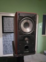
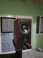
Yes, I'm resurrecting a somewhat old thread. I've got a pair of Mission 751s that I purchased 27 (!) years ago. The cabinets are fine, but the drivers are not aging gracefully. The rubber surrounds on the woofers have deteriorated to the point that they need to be changed, and the tweeter's "metal" dome (actually appears to be coated mylar or something similar) have lost their colour and have developed wrinkles that produce distortion peaks at higher frequencies.
Of course the drivers are no longer available, except 2nd hand, and I suspect that they probably would not last that long for the same reasons that the original ones failed.
For replacements, so far the best matches I've found that can fit without much if any changes to the enclosure are the Dayton DC130A woofer and the Peerless OC25SC65-04 tweeter, which is a good match for the faceplate if a simple DIY mounting bracket is used. Yes, it's a 4 ohm tweeter, but I'm going to have to redo the x-over anyway, so....
Anyway, a few things:
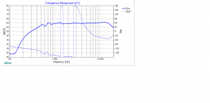
The extra "zing" at the top end of the 751's response seems to be a combination of a tweeter that's not padded down enough, and that shallow "waveguide" around the tweeter that seems to be boosting the response above 10kHz. Both can be somewhat corrected by x-over - I'm opting to address the first issue but not the second one, as that's going to require a few more components that may not fit on the terminal plate.
Comparing the x-over elements on my 751's terminal plate, it seems that they've made a number of changes. For example, inductor in the woofer's circuit is listed as 2 mH /0.40 Ohms in post #24, but DATS tells me that it's a 0.66 mH / 0.53 Ohms in 751's x-over circuit. The capacitor in the tweeter circuit is some blue thingy that measures 4.8 uF.
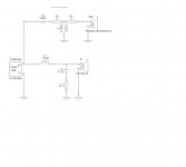
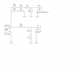
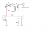
In any case, it's all gotta go, because the x-over, well the current version of the x-over that I plan to use with the new drivers requires entirely different components (see attached image). After desoldering the old components, how can I get them out of the terminal plate? Someone mentioned that hot water would loosen the glue - has anyone tried this?
Of course the drivers are no longer available, except 2nd hand, and I suspect that they probably would not last that long for the same reasons that the original ones failed.
For replacements, so far the best matches I've found that can fit without much if any changes to the enclosure are the Dayton DC130A woofer and the Peerless OC25SC65-04 tweeter, which is a good match for the faceplate if a simple DIY mounting bracket is used. Yes, it's a 4 ohm tweeter, but I'm going to have to redo the x-over anyway, so....
Anyway, a few things:
The extra "zing" at the top end of the 751's response seems to be a combination of a tweeter that's not padded down enough, and that shallow "waveguide" around the tweeter that seems to be boosting the response above 10kHz. Both can be somewhat corrected by x-over - I'm opting to address the first issue but not the second one, as that's going to require a few more components that may not fit on the terminal plate.
Comparing the x-over elements on my 751's terminal plate, it seems that they've made a number of changes. For example, inductor in the woofer's circuit is listed as 2 mH /0.40 Ohms in post #24, but DATS tells me that it's a 0.66 mH / 0.53 Ohms in 751's x-over circuit. The capacitor in the tweeter circuit is some blue thingy that measures 4.8 uF.
In any case, it's all gotta go, because the x-over, well the current version of the x-over that I plan to use with the new drivers requires entirely different components (see attached image). After desoldering the old components, how can I get them out of the terminal plate? Someone mentioned that hot water would loosen the glue - has anyone tried this?
Attachments
Hi Brian
I managed to simply lever mine out but maybe I was lucky - obviously have to be careful.
I'm sure the original design for the tweeter cap was 4.3 mf. When I removed the 2 inductors, they measured 0.62mH for the LF and 0.32mH for the HF - although as you say, it's not so relavent for you now as you are having to redesign yours.
Good luck, and let us know how you get on.
Interestingly enough, the component count actually does not go up (if I leave out the impedance linearizing "leg", e.g. the 1.8 uF capacitor and 6.2 ohm resistor), if I decide to trim the "zing" caused by the shallow waveguide around the tweeter. Basically one resistor is removed and an inductor is added, and the remaining resistor and capacitor are adjusted accordingly. I might just try this out...
Attachments
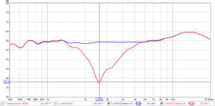
I'd be tempted to roll of that peerless tweeter a bit higher up as its res frequency is just under 1.4KHz?
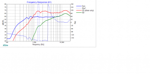
With the x-over in place, the tweeter's response is attenuated around 24dB at 1.4 kHz. Is this enough?
Attachments
Hi Brian. I don't know - I'm not an expert but with the crossovers I've worked on, I've tended to keep the response well away from the resonant frequency. My guess is that the tweeter could overheat easier with that demand on it. Hopefully somebody else could either confirm or repute that.
Are you sure the original tweeters are unusable/unrepairable? ..I know a few people think they are a little 'hot' but as you know, that can be addressed in the crossover.
Are you sure the original tweeters are unusable/unrepairable? ..I know a few people think they are a little 'hot' but as you know, that can be addressed in the crossover.
Last edited:
The tweeters are definitely unusable. The domes have wrinkles in them, and this is causing response variations and spikes in their distortion profiles.
For two previous x-over designs that I did, rather than going by the tweeter's Fs, I used the tweeter's distortion profile as a guide, setting the corner frequency at or higher at the point where the THD just started to ramp up. Those two designs are still going strong with no signs of tweeter failure. In this case however it was a case of choosing drivers to fit the box, rather than designing the box around the drivers. For this driver, the inflection point is around 2kHz, and the HP filter has the tweeter's output down -6dB net at this point.
For two previous x-over designs that I did, rather than going by the tweeter's Fs, I used the tweeter's distortion profile as a guide, setting the corner frequency at or higher at the point where the THD just started to ramp up. Those two designs are still going strong with no signs of tweeter failure. In this case however it was a case of choosing drivers to fit the box, rather than designing the box around the drivers
. For this driver, the inflection point is around 2kHz, and the HP filter has the tweeter's output down -6dB net at this point.Attachments
Interestingly enough, the component count actually does not go up (if I leave out the impedance linearizing "leg", e.g. the 1.8 uF capacitor and 6.2 ohm resistor),
Ummm ... you can probably dispense with "impedance linearizing" as modern amplfiers just don't care about that so long as it doesn't go low enough to do damage and adding parts chains that go to ground directly on the amplifier's output is just wasting energy.
Attachments
Hi Brian. I don't know - I'm not an expert but with the crossovers I've worked on, I've tended to keep the response well away from the resonant frequency. My guess is that the tweeter could overheat easier with that demand on it. Hopefully somebody else could either confirm or repute that.
Inductor, voice coil, impedance tend to rise at resonance. You won't likely damage it there, but it's likely to make an audible exaggeration in your frequency response.
Glad you were able to get them back up and running again. I found it was fairly easy to attach bigger caps (eg Audyn plus and Claritycap CSA's) and use cable ties to hold them in place (was a bit tight though) - worth looking into if you have a small amount of spare cash and time at a later date.
Ummm ... you can probably dispense with "impedance linearizing" as modern amplfiers just don't care about that so long as it doesn't go low enough to do damage and adding parts chains that go to ground directly on the amplifier's output is just wasting energy.
it doesn't cost that much extra, and it will ensure that the speakers' top end does not change significantly if it's driven by one of those cheaper class D "chip" amps. As it affects only stuff that's pretty high in frequency, the "wasted energy" is minimal.
- Status
- This old topic is closed. If you want to reopen this topic, contact a moderator using the "Report Post" button.
- Home
- Loudspeakers
- Multi-Way
- Mission 751 Crossover Circuit Diagram