Hello, you may be interested in trying this:
Online LEDR™ Sound Test | Listening Environment Diagnostic Recording Test
Haha! Oh thank you sir!
Yes! I will definitely try this absolutely, and more importantly this page has some excellent keywords and terminology that I have never heard of before to get me on the track to my own research. I have something to do searches on now and find other stuff.
Most excellent, oh I’ll be busy for at least a month with this thank you thank you.
@ ByRTT
So I got the cascade implemented just as you drew out.
And this time I did it right.
Sorry for all my double posts (it’s the old man in my spinning my wheels)
As far as this
What if those speakers don’t roll off picture perfect,
I’ve been using peq on the speaker output to shape things. Wouldn’t that affect the phase of other speakers? Should I be using global eq on everything?
Like my horns crossed at 1000LR4, do I match the drivers gains to form the crossovers so I can use global eq on everything? If I want every crossover and eq to globally affect everything which I realize is ideal how do I solve the +15db peak at 4K in my horns and the +6db peak at 1.6. On horns without killing the efficiency at the top end.
If global eq is ideal I’ll figure out a way to make it work.
So the results. Got it all dialed in and working and sounding great.
A few points
1. I had no idea that it would be noticed this much especially the horns and subs
Adding the 2nd low pass on the sub made the midbass sound like the crossover was dropped an oactave and everything sounds much more “open” and airy.
And the singer voice sounds more real and life like rather than sounding like coming out of a pair of speakers. I always thought about an oactave past the crossover the speaker is no audible so why would it matter. But it seems as if it’s not attenuating anything, it seems like adding the cascade pushes the timing on the sub and horns in a way that lines them up with all the midrange frequencies.
The snare has attack now where I’ve never really experienced that before. Very interesting trick, I’ll always do this now. So thank you!
2. To get the midbass to get this awesome effect that makes them seem to play lower and the sub sounds more in front , with the sub I basically had to turn off the time delay between the midbass and sub. It doesn’t make perfect sense yet but I think it’s the long wavelengths or the reverb time of some kind causing this. I had 2.5ms delay of the midbass to time alignment them to the sub and that seemed to make things worse with your cascade trick. I basically just have the sub and midbass all come out at same time now even tho there’s path length differences. Definitely a lot more ambiance down low especially and up front bass that I’ve never had before.
Now on to my question.
So if linearization makes the crossover spin disappear why do I have to have this cascaded crossovers on all speaker and the firs? Can anyone in a basic dummy way explain how that works. I’m trying to wrap my head around this, I’ve run all the sims in rephase to try to figure out why and can’t make sense of it.
Thanks in advance
Last edited:
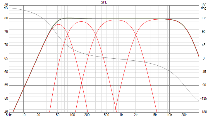
I'm not sure that you and Byrtt are on the same page. That graph is an idealised representation of the crossover points and slopes you could have in a 4 way system with 2nd order rolloff's added at either end, because the crossovers are linear phase they add back to form a minimum phase sum that that matches the amplitude.@ ByRTT
So I got the cascade implemented just as you drew out.
And this time I did it right.
Sorry for all my double posts (it’s the old man in my spinning my wheels)
As far as this
What if those speakers don’t roll off picture perfect,
I’ve been using peq on the speaker output to shape things. Wouldn’t that affect the phase of other speakers? Should I be using global eq on everything?
Like my horns crossed at 1000LR4, do I match the drivers gains to form the crossovers so I can use global eq on everything? If I want every crossover and eq to globally affect everything which I realize is ideal how do I solve the +15db peak at 4K in my horns and the +6db peak at 1.6. On horns without killing the efficiency at the top end.
If global eq is ideal I’ll figure out a way to make it work.
So if linearization makes the crossover spin disappear why do I have to have this cascaded crossovers on all speaker and the firs? Can anyone in a basic dummy way explain how that works. I’m trying to wrap my head around this, I’ve run all the sims in rephase to try to figure out why and can’t make sense of it.
Thanks in advance
To do that in reality means that you need to EQ each driver individually to flat at least an octave or two either side of the crossover with minimum phase EQ, time align then add textbook linear phase crossovers. The rolloff at either end will most likely not be textbook 2nd order but you can EQ to that if desired.
The idea of the global EQ is to use that to set your overall target curve and by doing that with minimum phase EQ you will not upset the crossovers that were EQ'd and aligned separately.
I'm not sure that you and Byrtt are on the same page. That graph is an idealised representation of the crossover points and slopes you could have in a 4 way system with 2nd order rolloff's added at either end, because the crossovers are linear phase they add back to form a minimum phase sum that that matches the amplitude.
To do that in reality means that you need to EQ each driver individually to flat at least an octave or two either side of the crossover with minimum phase EQ, time align then add textbook linear phase crossovers. The rolloff at either end will most likely not be textbook 2nd order but you can EQ to that if desired.
The idea of the global EQ is to use that to set your overall target curve and by doing that with minimum phase EQ you will not upset the crossovers that were EQ'd and aligned separately.
Okay thank you fluid!
So okay than I was doing it right..... that exactly how I’ve been doing it. As it says way back on the early pages. I’ve always measured every speaker flat at close mic an oactave past any crossover , than added all my linearizations or linear phase crossovers, than global eq to shape the magnitude.
This has always worked really good.
This cascade that BYRTT has definitely does something different. I’m getting better ambiance without a doubt. I just adopted his blocks and dropped my LR4s in instead of what he has and my crossover points. So now I’m really confused.
In a car it’s almost impossible to get good measurements globally as the near reflections add way too much excess phase so windowing has to be pretty aggressive compared to the room size.
Doing the cascade the phase drops a lot like his picture where how I was doing it was more flat. They both sound good, the cascade has more ambiance. Not sure if that means better, but so far seems good. I like them both, but his cascade seems better, I’ll have to listen for a week to really say for sure.
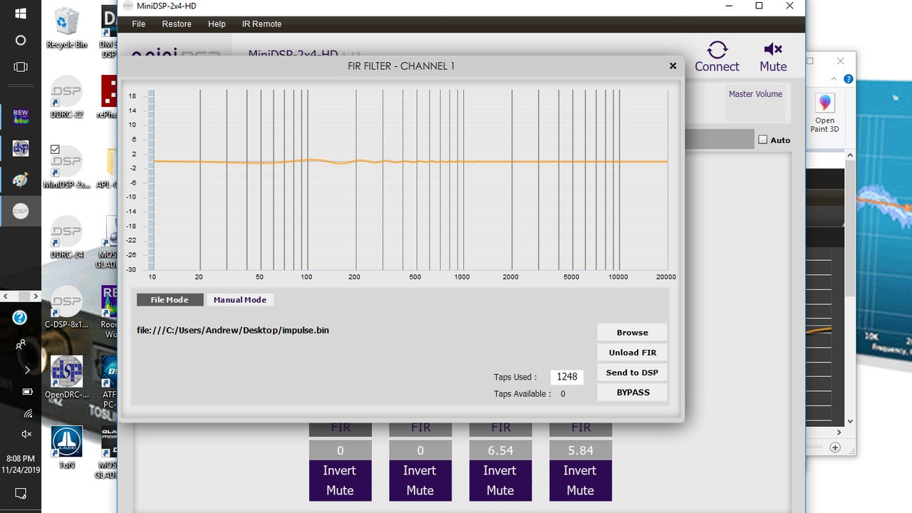
So my system is basically this
3 2x4hds to a 4way all linear phase crossovers in the fir banks
1 opendrc upstream of the HDs with gloabal eq and the linearization parts of his cascade in the fir blocks.
The HD’s I used a peq bank in advanced to get the added crossovers for each speaker in iir, and again used the opendrc to do linearizations gloabally on everything.
So each speaker gets all the linearizations gloabally on the opendrc and it’s own crossovers and IIrs seperate on the HDs along with the initial fir crossover for the inband of each driver
The blocks form just like his diagram
It’s sorta goofy I might have done it wrong, the ambiance sounds a little artificial almost like reverb ish sounding. So either I botched it or it just needs a little more fine tuning
It was like 12 linearizations done gloabally on the opendrc , the phase turned from flat to a LOT of lines going through the magnitude like stripes , the phase just looked like lots of lines going from top to bottom over and over again in rephase , the measured phase was more down hill tho ......
Last edited:
Byrtt can confirm when he sees your post but I am fairly confident that the blocks that you refer to as "cascade" are just what is needed to represent those curves in Xsim.
I don't think the idea is to try and input those as corrections.
The reason the phase curves more at the bottom and top is because the magnitude is rolling off. If your magnitude does not roll off in that way then you don't want the phase to either. The low one is 2nd order Q 0.83 at 45Hz which is the figures you provided earlier, so it's a virtual representation of that.
If you like what all that unnecessary correcting does measure it and see if you can work out why")
I don't think the idea is to try and input those as corrections.
The reason the phase curves more at the bottom and top is because the magnitude is rolling off. If your magnitude does not roll off in that way then you don't want the phase to either. The low one is 2nd order Q 0.83 at 45Hz which is the figures you provided earlier, so it's a virtual representation of that.
If you like what all that unnecessary correcting does measure it and see if you can work out why
Byrtt can confirm when he sees your post but I am fairly confident that the blocks that you refer to as "cascade" are just what is needed to represent those curves in Xsim.
I don't think the idea is to try and input those as corrections.
The reason the phase curves more at the bottom and top is because the magnitude is rolling off. If your magnitude does not roll off in that way then you don't want the phase to either. The low one is 2nd order Q 0.83 at 45Hz which is the figures you provided earlier, so it's a virtual representation of that.
If you like what all that unnecessary correcting does measure it and see if you can work out why
Thank you again Fluid
So this morning I went and listened again. (Fresh ears)
I starting taking off the added cascade one by one as it didn’t sound as natural as before.
So the part that I liked was having the 300hz low pass along with the 80hz low pass on the sub only. After reducing down and mixing out what seemed wrong the added lowpass cascade to the sub definitely sounds better.
I ended up taking everything else off and went back to the standard linear crossovers.
So I think I’ll keep it like this for awhile and like you said try and figure out why.
It makes the midbass sound like there playing sub frequencies. It’s a fantastic effect.
The car is 2.66ms wide so the 300hz crossover is right in that area. Maybe just a artifact of reflection and interference that adding the 2nd lowpass seems to help.
(Just a guess) or BYRTT is right and I’m not understanding him again.
As far as his diagram, even if it was from xsim and justba way to show theoretical flat phase with a 4way, wouldn’t that technique still apply in real life.
I think he is on to something and I just haven’t grasped it maybe.
Or I simply don’t have the processing to do it exactly like he shows.
If each one of his lines in the block reads right to left and each row is a single channel an should not be global than I just don’t have the process power to do it. (I wish the HDs had a 48k plugin)
The sub has 2042 t
Everything else only 1024 t
The opendrc has 6144 t
So I think I would need a opendrc on every pair of speakers to be able to do the
cascade on each speaker pair as he has it in rows , maybe trying to do all the linearizations on the opendrc wasn’t correct and caused the reverb ish sound.
Hi Oabeieo,
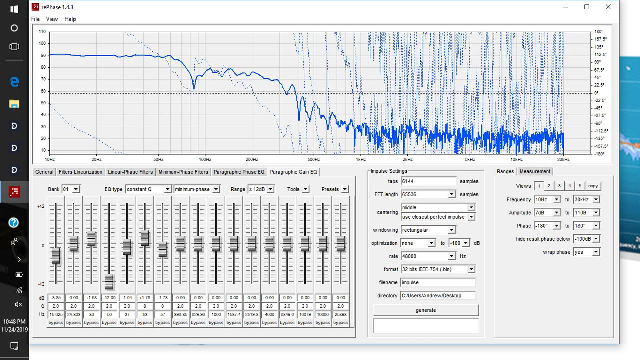
Know it can be hard to grasp therefor suggest you take some virtual study to educate your self, it is not that hard copy my example pass bands in Rephase export them as frd files import to REW where you can sum them on "ALL SPL" tab using the wonder math it can offer in "Controls" dialog. You will then see example sum perfect as was it one pointsource transducer, and when you do the same exercise but omit side and stop bands you get varius errors in amplitude and phase domains no matter you use FIR or IIR XO slopes.
Understand its a textbook example to get four way sum perfect flat when looked isolated from a real indoor enviroment, at the same we place that system into a indoor enviroment we get tons of extension in low end and ugly ripple from bounderys, but it doesn't change on that the optimal relation between pass bands is as in the example, to count for room gain plus ripple plus dial in the right house curve for system installation shall use global correction to form a perfect integration sum of the optimal textbook multi way with the room enviroment gain signature.
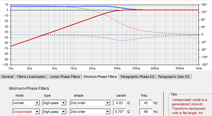
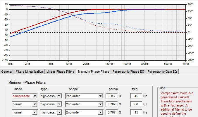
For example say you room enviroment gain signature was a friendly curve looking exactly as was it a linktwitz transform from Q0,83 @45Hz to Q0,7 20Hz, then we was set and happy in system pass band is now a flat minimum phase domain covering 20Hz-20kHz audio band.
Another note is i noticed my box simulation program in good old WinSpeakerz model auto cabin response as a linkwitz transfer from Q0,7071 @66Hz flat down to DC point (0Hz), if that is right think you should try transfer your system stopband in global EQ from Q0,83 @45Hz to Q0,7 @66Hz and set a 2nd order highpass in area 15-20Hz.
Know it can be hard to grasp therefor suggest you take some virtual study to educate your self, it is not that hard copy my example pass bands in Rephase export them as frd files import to REW where you can sum them on "ALL SPL" tab using the wonder math it can offer in "Controls" dialog. You will then see example sum perfect as was it one pointsource transducer, and when you do the same exercise but omit side and stop bands you get varius errors in amplitude and phase domains no matter you use FIR or IIR XO slopes.
Understand its a textbook example to get four way sum perfect flat when looked isolated from a real indoor enviroment, at the same we place that system into a indoor enviroment we get tons of extension in low end and ugly ripple from bounderys, but it doesn't change on that the optimal relation between pass bands is as in the example, to count for room gain plus ripple plus dial in the right house curve for system installation shall use global correction to form a perfect integration sum of the optimal textbook multi way with the room enviroment gain signature.
For example say you room enviroment gain signature was a friendly curve looking exactly as was it a linktwitz transform from Q0,83 @45Hz to Q0,7 20Hz, then we was set and happy in system pass band is now a flat minimum phase domain covering 20Hz-20kHz audio band.
Another note is i noticed my box simulation program in good old WinSpeakerz model auto cabin response as a linkwitz transfer from Q0,7071 @66Hz flat down to DC point (0Hz), if that is right think you should try transfer your system stopband in global EQ from Q0,83 @45Hz to Q0,7 @66Hz and set a 2nd order highpass in area 15-20Hz.
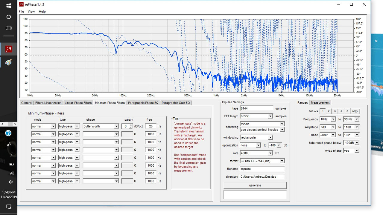
Maybe I confused you before saying not to input them directly, I should have said if you want to look at the cascade of filters ignore the low and high ones as they represent the system stop bands in the simulation and may not be what you have.
If you cascade the three crossovers slopes you will see what effect it has.
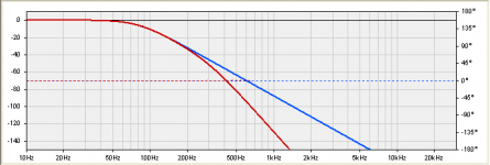
Here is an example using the low driver, comparing the LR24 at 80HZ in blue to the cascaded version using LR24 at 80Hz and LR24 at 300Hz.
The start of the rolloff is the same but gets to be a 48dB filter further along.If you add in the 2000Hz filter the change happens somewhere around -140dB so for real use it would be fairly safe to leave it out.
You could do the same thing by cascading the LR24 filters with IIR and then use filters linearization in a global FIR to undo the phase turn of the crossover filters. That would likely save you taps in your mindsp units.
Maybe it is this change in crossover slope that you like. The change only happens at -40dB so in reality it should be a fairly subtle effect.
If you cascade the three crossovers slopes you will see what effect it has.
Here is an example using the low driver, comparing the LR24 at 80HZ in blue to the cascaded version using LR24 at 80Hz and LR24 at 300Hz.
The start of the rolloff is the same but gets to be a 48dB filter further along.If you add in the 2000Hz filter the change happens somewhere around -140dB so for real use it would be fairly safe to leave it out.
You could do the same thing by cascading the LR24 filters with IIR and then use filters linearization in a global FIR to undo the phase turn of the crossover filters. That would likely save you taps in your mindsp units.
Maybe it is this change in crossover slope that you like. The change only happens at -40dB so in reality it should be a fairly subtle effect.
Attachments
Last edited:
Hi Oabeieo,
Know it can be hard to grasp therefor suggest you take some virtual study to educate your self, it is not that hard copy my example pass bands in Rephase export them as frd files import to REW where you can sum them on "ALL SPL" tab using the wonder math it can offer in "Controls" dialog. You will then see example sum perfect as was it one pointsource transducer, and when you do the same exercise but omit side and stop bands you get varius errors in amplitude and phase domains no matter you use FIR or IIR XO slopes.
Understand its a textbook example to get four way sum perfect flat when looked isolated from a real indoor enviroment, at the same we place that system into a indoor enviroment we get tons of extension in low end and ugly ripple from bounderys, but it doesn't change on that the optimal relation between pass bands is as in the example, to count for room gain plus ripple plus dial in the right house curve for system installation shall use global correction to form a perfect integration sum of the optimal textbook multi way with the room enviroment gain signature.
For example say you room enviroment gain signature was a friendly curve looking exactly as was it a linktwitz transform from Q0,83 @45Hz to Q0,7 20Hz, then we was set and happy in system pass band is now a flat minimum phase domain covering 20Hz-20kHz audio band.
Another note is i noticed my box simulation program in good old WinSpeakerz model auto cabin response as a linkwitz transfer from Q0,7071 @66Hz flat down to DC point (0Hz), if that is right think you should try transfer your system stopband in global EQ from Q0,83 @45Hz to Q0,7 @66Hz and set a 2nd order highpass in area 15-20Hz.
Thanks BYRTT,
Alright that is making a lot more sense now. Sorry for thinking it was something different. For some reason I thought that was a model to try on a multi-way.
So it’s going to take a little bit to digest this, I thought I was on to my next revelation in learning, okay so taking a step back now,I’ll definitely try that and see what happens.
So, going back to my original post. The closed box linearization that I asked about. I think what I’m trying to figure out or learn in a simple way is.
Let’s say out of the car the box rolls off at f345 QTC.83, in car I get fairly flat to about 16hz. I do have to use eq at 66hz (you hit that on the head) and take it down -6db peq Q 1.4 to be flat to 20
My question is, if the box , the cabinet causes a natural roll off at 45hz but the room boosts below it and you say it acts as a Linkwitz Transform, that would mean it’s minimum phase and doesn't need any farther work done from Rephase
I was wondering I guess if room gain is minimum phase now that I think about it
So I did end up learning off this, not what I expected to learn but still beneficial indeed
I’ll try and find some reading
Thanks again
My question is, if the box , the cabinet causes a natural roll off at 45hz but the room boosts below it and you say it acts as a Linkwitz Transform, that would mean it’s minimum phase and doesn't need any farther work done from Rephase
I was wondering I guess if room gain is minimum phase now that I think about it
That was pretty much the discussion that was had above. If you linearize the sealed box you will change the phase away from minimum and end up with a phase that does not follow the amplitude response.
Measure the result you have and use REW with a FDW to clean up the phase, generate a minimum phase version in REW and compare to what you have. If there's excess phase you can export that and use rephase to try and correct for it and see if you like that any better.
...My question is, if the box , the cabinet causes a natural roll off at 45hz but the room boosts below it and you say it acts as a Linkwitz Transform, that would mean it’s minimum phase and doesn't need any farther work done from Rephase
I was wondering I guess if room gain is minimum phase now that I think about it...
First will say remember room is global so don't count its corrections dedicated for the lowest pass bands but as global for the summed system passband, and yes room gain is of minimum phase except the reflections that arrive late at listening position, one can repair late reflections but think forget about it because correction only works at that particular spot in space where microphone was positioned. Reflection free is no room but we can get superior sound with a perfect dialed in speaker system corrected for room gain and a house curve that is tweaked to suit the speaker/room profile.
Below is sim model your system HP stopband with the red curve, you can see the numbers in first row, next i set the program WinSpeakerz model for auto cabin response with the numbers in second row. Now look the blue curve it is hot and worthless in you get a flat boost all the way down to DC, this will sound bloated with DC thumbs and mud sound signature way up into higher frq.
Cure for that if WinSpeakerz model is spot on is a linkwitz transform as the first two rows below, first it linearize your HP stopband to flat in row 1 then in row 2 the new 66Hz HP stopband is set, now we are flat down to DC because remember your system is at 2nd order 66Hz corner and auto cabin response boost a 2nd order 66Hz flat down to DC, therefor set some HP filter in area 15-20Hz (15Hz 2nd order used below). Overall correction is the blue curve and red curve is your new speaker plus room HP response, hope it makes sense ...
Attachments
That was pretty much the discussion that was had above. If you linearize the sealed box you will change the phase away from minimum and end up with a phase that does not follow the amplitude response.
Measure the result you have and use REW with a FDW to clean up the phase, generate a minimum phase version in REW and compare to what you have. If there's excess phase you can export that and use rephase to try and correct for it and see if you like that any better.
Perfect answer thank you!
I love getting steps to follow. That helps so much.
So one thing I learned big time from the conversation is that the crossover shifts more than just the spin. This is invaluable to me. It seems as if a low pass moves everything below it back a little bit.
So my next step beyond making linearized crossovers is trying to attempt a room correction. I wanted to get the crossovers done right and I’m think I’m there for the most part. I’m sure there’s some that could be better, but it’s fairly good I think. This conversation definitely helps me know what’s going on.
I have run countless sims with rephase to study what the phase does when I apply all kinds of situations with no measurement imported just to see what it looks like and that too has taught me a lot but I can say I’ve never noticed how the phase gets moved back all the way into the lows from the highs. So this is great.
But this brings up another question now.
So I’ve been running more sims just now noticing this effect an it makes me wonder how using peq on each channel/speaker output and not gloabal eq isn’t detrimental.
In my case I have 12ch of dsp (I’m only using 10) I have front door midbass , kickpanel midrange , Horns , subs, rear door midbass. If I do close mic measurements and make all of them flat prior to any global eq for listening position measurements and eq would not the phase be scattered all over the place?
Earlier you said time align the drivers. Which I’ve done using tape measure distance, wouldn’t the peq change the time at some frequencies and not others?
If this effect happens wouldn’t the driver peq be detrimental to the timing of everything? If a lot of eq is required couldn’t it be as bad as randomly putting on an APF in places it doesn’t belong?
Seems to me now gloabal eq is the only acceptable eq to use if this is what happens.
As an experiment I just tried turning off all my other eq and tried using only gloabal eq (it was quick n dirty but just to see) and it definitely seems better in some ways. But I can’t say for sure
What do you think, how does that part function?
First will say remember room is global so don't count its corrections dedicated for the lowest pass bands but as global for the summed system passband, and yes room gain is of minimum phase except the reflections that arrive late at listening position, one can repair late reflections but think forget about it because correction only works at that particular spot in space where microphone was positioned. Reflection free is no room but we can get superior sound with a perfect dialed in speaker system corrected for room gain and a house curve that is tweaked to suit the speaker/room profile.
Below is sim model your system HP stopband with the red curve, you can see the numbers in first row, next i set the program WinSpeakerz model for auto cabin response with the numbers in second row. Now look the blue curve it is hot and worthless in you get a flat boost all the way down to DC, this will sound bloated with DC thumbs and mud sound signature way up into higher frq.
Cure for that if WinSpeakerz model is spot on is a linkwitz transform as the first two rows below, first it linearize your HP stopband to flat in row 1 then in row 2 the new 66Hz HP stopband is set, now we are flat down to DC because remember your system is at 2nd order 66Hz corner and auto cabin response boost a 2nd order 66Hz flat down to DC, therefor set some HP filter in area 15-20Hz (15Hz 2nd order used below). Overall correction is the blue curve and red curve is your new speaker plus room HP response, hope it makes sense ...
Would it help to post room responses for sub?
I can do that , if so should I turn off all eq ?
Last edited:
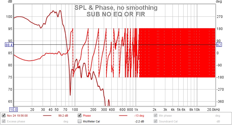
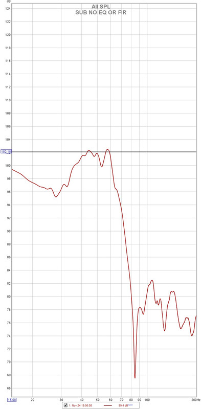
so here is some measurements of just the sub at listening position, I also took screenshots of the eq pages even tho its not in measurements.
In can post up the actual file or send it if it helps.
I would love to know what to do!
the sub seems like the hardest part to get sounding the best
Super dooper appricated !!!

host photos online

In can post up the actual file or send it if it helps.
I would love to know what to do!
the sub seems like the hardest part to get sounding the best
Super dooper appricated !!!
host photos online
View attachment sub.zip
here is the mdat
And those measurements do have the linearizations applied and a 80hz crossover applied
There’s a big dip I don’t know what to do with and all that room gain
here is the mdat
And those measurements do have the linearizations applied and a 80hz crossover applied
There’s a big dip I don’t know what to do with and all that room gain
Last edited:
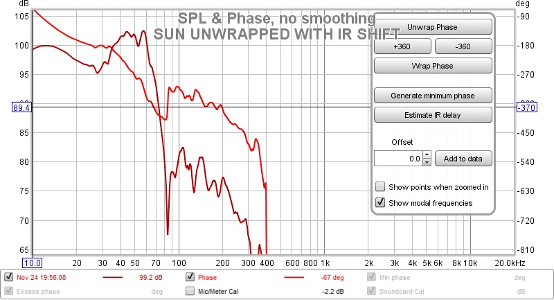
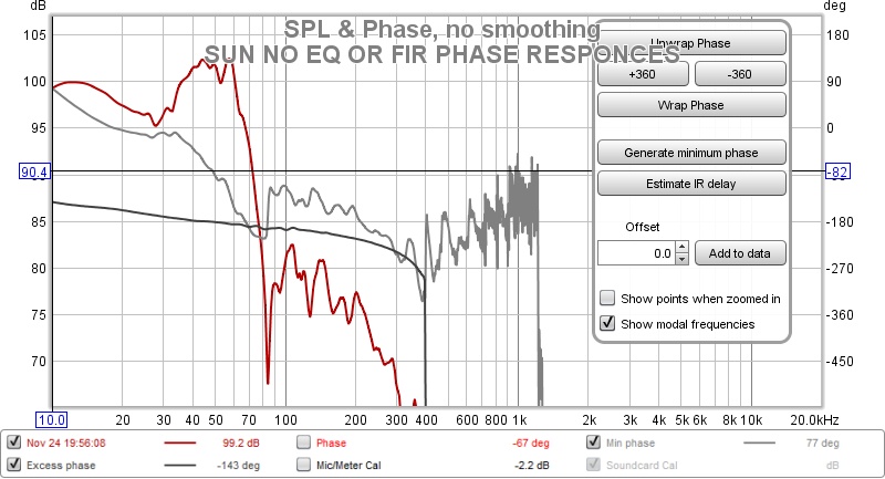
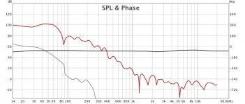
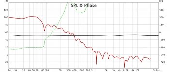
so I did this in rephrase, it sounds good..much better with butterworth 6db 20hz hpf
but I don't know what to do with excess phase.....
do I make it flat? look at that around 80hz geesh
this is what I meant by hard to figure out sub measurements...the midbass was much easier
RED is unchanged measurement, blue is the correction ....what am I missing

but I don't know what to do with excess phase.....
do I make it flat? look at that around 80hz geesh
this is what I meant by hard to figure out sub measurements...the midbass was much easier
RED is unchanged measurement, blue is the correction ....what am I missing
I don't understand what is in the mdat is it a raw driver response or with correction ? And if so what correction.
Attached is a low cycle FDW with generated minimum phase to show what it should look like and another with what is in the mdat. The phase goes the wrong way in yours which makes me think you have processed it.
The phase jump at around 85Hz is a boundary interference null. I think you will probably have to leave that alone unless you can treat it acoustically somehow.
Attachments
I don't understand what is in the mdat is it a raw driver response or with correction ? And if so what correction.
Attached is a low cycle FDW with generated minimum phase to show what it should look like and another with what is in the mdat. The phase goes the wrong way in yours which makes me think you have processed it.
The phase jump at around 85Hz is a boundary interference null. I think you will probably have to leave that alone unless you can treat it acoustically somehow.
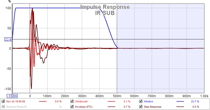
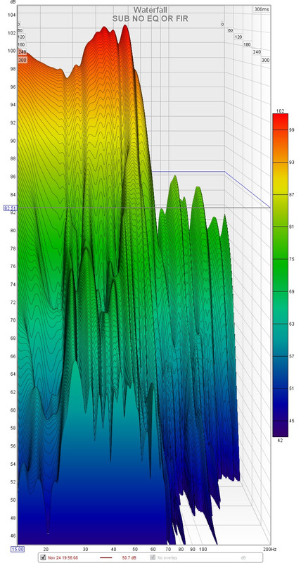
Sub only at listening position
No eq just crossover turned on and textbook 80hz linearization
When I took that I just plugged my sound card right into the minidsp that runs sub , so it was missing eq
I was hoping to see what I should do about the excess phase around 70-80 hz
And elsewhere and just post it so it could be seen as what I should actually be doing with the sub.
Aha ! So I won’t mess with that than. Yes a back window is in the way !
I thought weren’t supposed to use FDW on subs. I thought it was all minimum phase and didn’t need it (what I read awhile back) so this is interesting
Last edited:
FLUID & BYRTT
so I went from mediocre sounding bass that as too fat and deep to
Very nice (very very nice) sounding bass
Guys I can’t say how much I appreciate the help
The 6db subsonic really cleaned things up, and I didn’t know what else to eq because I didn’t know what eq or where to use the eq.
I always did it on the sub output now it’s gloabal , and wow the system sounds so much better now.
The horns sound way more in tune with the bass it’s ridiculous how much better it is.
The 80hz phase issue is what it is. Still sounds way better than before.
I lost a ton of gain but it’s still plenty loud enough for me.
The 12db BW subsonic sounded like too much of the very bottom end was taken out
The 6db BW sounds great, (that was the best improvement)
I think I’m getting there now. It’s way better than I’ve ever had it.
I just took off the cascade and went back to standard linear phase crossovers
I think the subsonic is the timing issue that made things sound weird and off time.
I know it’s rookie but way better than I’ve ever had so thanks so much!
The drive to work was amazing this morning!
It would probably be useful to get a measurement without any processing or EQ, to see what the basic driver response is. With that sort of cabin gain you might be better off eq'ing the slope to what you want rather than flattening and using a textbook crossover. You might get some gain back that way.Sub only at listening position
No eq just crossover turned on and textbook 80hz linearization
When I took that I just plugged my sound card right into the minidsp that runs sub , so it was missing eq
Try a close mic measurement as well to see the difference in phase, because something is sending your phase the wrong way.
FDW is just different gate lengths at different frequencies and can be helpful to see the direct wavefront before it gets messed up by the room/cabin. In your measurement reflections are happening early due to the small space. I don't understand what a FDW and minimum phase have to do with each other?Aha ! So I won’t mess with that than. Yes a back window is in the way !
I thought weren’t supposed to use FDW on subs. I thought it was all minimum phase and didn’t need it (what I read awhile back) so this is interesting
Why not use it if it helps you to see what is happening?
- Home
- Design & Build
- Software Tools
- rePhase, a loudspeaker phase linearization, EQ and FIR filtering tool