my subw's design is isobaric, working bandpass. inside the band, there is a huge dip around 54Hz (central freq). same dip exists in main speakers. subw signal is being cut on my subw amp (LPF ~100Hz).
same dip exists in the measurement of main speakers.
after having computed excess group delay, GD chart of REW indicates a peak in group delay as ~90ms right at 68Hz (central freq).
i would like to deploy rePhase, however does not have enough knowledge. i cannot determine the cause of the problem; is it due room mode, is it just a simple magnitude problem that can be smoothed out with EQ? actually, i am confused.
that is why i am asking for solid books to gain a solid understanding of hifi system - environment relationship.
I don't have good book references to give you specifically on measurement techniques (and then loudspeaker and room measurement are also two different subjects, albeit closely related...).
One thing for sure: you should get a proper integration first before even trying to add phase linearization into the mix (that is, unless you are using a FIR crossover).
Last edited:
If your target is a minimum phase response (ie you don't linearize the phase of the system's high/low pass) and your crossover are summing properly in a large enough angle, then you should not get any pre ringing.
Pos, I'm not sure I fully understand what you mean by what I marked with bold. Do you mean in-phase crossovers don't work? If you know of a good example of a speaker for which rephase was used to correct phase distortion caused by the crossover, I'd love a link.
I mean a proper in-phase summation over a large enough angle is what one should be looking for.
That implies time aligned drivers (preferably geometrically), directivity matching, and not-to-sharp slopes.
The perfect text book example (albeit not done with rephase) is the one in the Grimm Audio LS12 loudspeaker.
That implies time aligned drivers (preferably geometrically), directivity matching, and not-to-sharp slopes.
The perfect text book example (albeit not done with rephase) is the one in the Grimm Audio LS12 loudspeaker.
Last edited:
Err, I meant LS1 : http://www.grimmaudio.com/site/assets/files/1088/speakers.pdfGrimm Audio LS12 loudspeaker.
Keyser, I reread the conversation and I think there must be a misunderstanding somewhere, probably because I was not clear enough.
I totally agree with the principle of in-phase crossover summation, as advocated by Linkwitz
")
I've worked with rephase to correct the phase distortion of a 2-way LR8 filter on a speaker with drivers that have a very well-behaved response and dispersion and of which the drivers are acoustically aligned. No matter what I do, I always seem to be getting some pre-ringing. Going with less steep crossovers helps, but does not eliminate the issue.
I've looked at the LS1 (which seems to be a very well-designed speaker by the way) and their step response actually does show some minor pre-ringing (see page 6: http://www.grimmaudio.com/site/assets/files/1088/speakers.pdf). Probably inconsequential, but it is there. I have always thought that pre-ringing was an inevitable result of correcting crossover phase and that its inevitability could be proven mathematically. Are you sure that is not the case? Intuitively to me it makes sense there has to be some pre-ringing, because when you visually inspect the filter it appears to be doing things well before the actual peak. But I guess I need to educate myself on the matter.
I've looked at the LS1 (which seems to be a very well-designed speaker by the way) and their step response actually does show some minor pre-ringing (see page 6: http://www.grimmaudio.com/site/assets/files/1088/speakers.pdf). Probably inconsequential, but it is there. I have always thought that pre-ringing was an inevitable result of correcting crossover phase and that its inevitability could be proven mathematically. Are you sure that is not the case? Intuitively to me it makes sense there has to be some pre-ringing, because when you visually inspect the filter it appears to be doing things well before the actual peak. But I guess I need to educate myself on the matter
.I've worked with rephase to correct the phase distortion of a 2-way LR8 filter on a speaker with drivers that have a very well-behaved response and dispersion and of which the drivers are acoustically aligned. No matter what I do, I always seem to be getting some pre-ringing.
What was the frequence of this pre-ringing? A part of it, as seen in Grimm pdf, may come from the dac:
https://www.ayre.com/pdf/Ayre_MP_White_Paper.pdf
Agreed, the preringing probably comes from the DAC's antialiasing filter.
A linear phase filter will have pre (and post) ringing, but the ringing of complementary high and low pass linear phase filters will cancel.
But this cancellation requires the filters to be complementary, which in turn calls for a well matched directivity behavior if you want this to be the case off axis over a reasonable angle.
Last edited:
I've worked with rephase to correct the phase distortion of a 2-way LR8 filter on a speaker with drivers that have a very well-behaved response and dispersion and of which the drivers are acoustically aligned. No matter what I do, I always seem to be getting some pre-ringing. Going with less steep crossovers helps, but does not eliminate the issue.
I've looked at the LS1 (which seems to be a very well-designed speaker by the way) and their step response actually does show some minor pre-ringing (see page 6: http://www.grimmaudio.com/site/assets/files/1088/speakers.pdf). Probably inconsequential, but it is there. I have always thought that pre-ringing was an inevitable result of correcting crossover phase and that its inevitability could be proven mathematically. Are you sure that is not the case? Intuitively to me it makes sense there has to be some pre-ringing, because when you visually inspect the filter it appears to be doing things well before the actual peak. But I guess I need to educate myself on the matter
What was the frequence of this pre-ringing? A part of it, as seen in Grimm pdf, may come from the dac:
https://www.ayre.com/pdf/Ayre_MP_White_Paper.pdf
Agreed, the preringing probably comes from the DAC's antialiasing filter.
A linear phase filter will have pre (and post) ringing, but the ringing of complementary high and low pass linear phase filters will cancel.
But this cancellation requires the filters to be complementary, which in turn calls for a well matched directivity behavior if you want this to be the case off axis over a reasonable angle.
keyser,
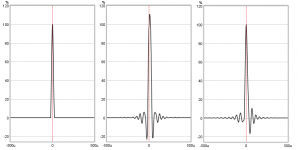
Beside jmbee and pos good answers pointing to ADC/DAC's, one also can add more excess pre ringing if in measurement setup combination of software verse hardware verse OS is not in sync, below is example of that see more detail in post 1047.
Attachments
.....I've looked at the LS1 (which seems to be a very well-designed speaker by the way) and their step response actually does show some minor pre-ringing (see page 6: http://www.grimmaudio.com/site/assets/files/1088/speakers.pdf). Probably inconsequential, but it is there. I have always thought that pre-ringing was an inevitable result of correcting crossover phase and that its inevitability could be proven mathematically. Are you sure that is not the case? Intuitively to me it makes sense there has to be some pre-ringing, because when you visually inspect the filter it appears to be doing things well before the actual peak. But I guess I need to educate myself on the matter
Guess whatever small pre ringing in LS1 paper is their ADC/DAC's or sample rate conversion, about math behind myself got curious and did a small live study. IR in third plot is pretty clean so filters math seems okay and think if reality show other it must be other components in chain or use of wrong filters. In live study use SPDIF loop to rule out distortion from ADC/DAC chain.
Attachments
Last edited:
Hi BYRTT,
Problem with the step response graphic is the DC component.
(as shown with corrected signal)
step response is the integral of the impulse.(1 ---> 1/s)
Dirac function (or delta func.) include large amount of very low frequency (see DC component).
The use of soundcard (spdif or other way) is limiting the bandwidth.(transformer or serie capacitor).and of course missing components
Can get a try with a scopemeter.(step response or square wave).
Last edited:
Hi thierry38,
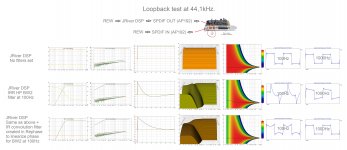
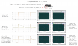
Thanks input unfortunate not shure i understand 100% other than agree amplitude energy (DC component) is missing in the one with IRR BW2 HP filter plus FIR phase convolution correction. You mention squarewave find it visualized below in a live run including REW IR/SR windows from previous run but this time presented with other X/Y scale settings.
Think study, in its a real live run via SPDIF show that math behind which keiser was questioning do not add that small pre ringing we happen see for some, also in that IRR filter is programmed by JRiver company and convolution filter is programmed by pos show us there filters is precise and working as they should : )
Attachments
.....The use of soundcard (spdif or other way) is limiting the bandwidth.(transformer or serie capacitor).and of course missing components...
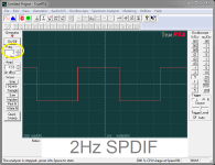
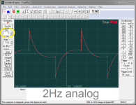
SPDIF code seems have instructions for DC component no matter transformer or capacitor in the interface, AP192 have 4 channels two of them SPIDIF and two normal analog, see below when they looped a 2Hz squarewave : )
Attachments
I've been lurking here hoping to slowly learn about rePhase and I'm very impressed with the knowledge and generosity of the thread's contributors. For now, I'm trying to extract all of the potential DSP goodness from an ARMhf board, the BBB. It is running the adaptive kernel known as 'Botic' as a renderer of asynchronous server data with mostly IIR filters. Looking for improvements, I'm just now experimenting with FIR. I don't want to pollute this thread, but I would especially appreciate any expert comments and suggestions over at this linked thread.
TIA,
Frank
TIA,
Frank
The imported measurement curve is only used as a guide and has no direct incidence on the generated FIR.
It is convenient to set the measurement gain offset so that the magnitude curve is close to 0dB in order to be able to use the different range settings and presets, and also be able to toggle the measurement bypass button without changing the range.
This bypass function will let you check the actual level of your correction, and you will typically want to make sure it does not exceed 0dB.
The imported measurement curve is only used as a guide and has no direct incidence on the generated FIR.
It is convenient to set the measurement gain offset so that the magnitude curve is close to 0dB in order to be able to use the different range settings and presets, and also be able to toggle the measurement bypass button without changing the range.
This bypass function will let you check the actual level of your correction, and you will typically want to make sure it does not exceed 0dB.
Thanks Pos
Hi,
I am making new raw driver measurements, this time using REW instead of ARTA.
I am trying to export frequency response to load it in rephase.
Can someone advice how to save minimum phase information through REW?
I am getting wrapped phase when i load the exported frd in rephase. I cant use that to perform the flattening
Help is appreciated.
thanks
Hi,
wrap phase (control tab),put a 1/3 smoothing and add a large IR windows (flat top type for example),about 20~40ms.
To save it,this can be done in 2 (quick) steps.
1-export impulse with minimum phase
2-import the impulse (above)
3-export measurements as text.
wrap phase (control tab),put a 1/3 smoothing and add a large IR windows (flat top type for example),about 20~40ms.
To save it,this can be done in 2 (quick) steps.
1-export impulse with minimum phase
2-import the impulse (above)
3-export measurements as text.
Last edited:
Can someone advice how to save minimum phase information through REW?
Hi,
For a single driver, phase and minimum phase are supposed to be nearly equal, after fine tuning t= 0 on the impulse.
- Home
- Design & Build
- Software Tools
- rePhase, a loudspeaker phase linearization, EQ and FIR filtering tool