One might wonder where the ringing is worst in the equipment.
Load that equipment IR into REW and look at the (very) early waterfall plot. I bet it will only show ringing at very high frequencies. Close to it's cut off frequency.
Weather it shows in actual measurements would still be a question, Though your high frequencies are extended enough.
To add another thought, the IR you show is DAC or soundcard out to Mic/Line in, right? Did you apply any calibration to it?
The reason I ask is I had my mic calibration still on (as for regular measurements), but the mic isn't inline. To show my real IR I had to remove that Cal file in REW.
Last edited:
How do you mean? As far as I recall, the cal file is only applied to the FR.The reason I ask is I had my mic calibration still on (as for regular measurements), but the mic isn't inline. To show my real IR I had to remove that Cal file in REW.
I spent some time creating a 44.1k measuring system calibration IR (soundcard, Pre-Pro, DCX2496, P-amp, and mic). I had many difficult issues, but did get the expected results on 1 or 2 trials; enough to see that the expected improvement in the appearance of the step response occurred and that SPL and phase were still correct. I never got it refined as a simple reliable process.
For me, the other charts tell the whole story anyway so there was no practical need to get it working reliably. It did make the step response look much better, but once the visual impact on the ringing on the charts was confirmed it could just be ignored. This was my approach for some time.
More recently I shifted my sample rate for the measuring system to 96k so the ringing is gone now. My music is all 44.1k so I just make the rePhase FIR filter at both sample rates and load the one that's needed. The measurements then do not take into account the impact of the 44.1k reconstruction filter on the sound, but that is likely to be a minor concession in terms of impact on sound quality.
The Holm impulse manual has a description of each function in lay person terms. Basically A+B is like playing 2 drivers at the same time and measuring the result, A-B is same but 1 driver inverted, A*B is like applying a filter, A/B is like applying a mic cal file (aka like applying the inverse of a filter), (A+B)/2 is averaging but can also be used to copy a single measurement. Bear in mind the window and smoothing from trace A will be applied to the result.Hi, yes..."Estimate IR delay" has become a very routine step ...
Trying to learn more about arithmetic operations, A vs B......do you have any recommended links?
Going to 3ll3d00d's link now....
The link was just a description of a process, you'd need to write the code to do this yourself (can be done in python for example)
One might wonder where the ringing is worst in the equipment.
Load that equipment IR into REW and look at the (very) early waterfall plot. I bet it will only show ringing at very high frequencies. Close to it's cut off frequency.
Weather it shows in actual measurements would still be a question, Though your high frequencies are extended enough.
To add another thought, the IR you show is DAC or soundcard out to Mic/Line in, right? Did you apply any calibration to it?
The reason I ask is I had my mic calibration still on (as for regular measurements), but the mic isn't inline. To show my real IR I had to remove that Cal file in REW.
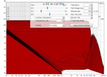
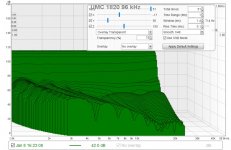
Here's a water fall of the x-32. I'm not sure how to set time settings for best look, so they are shown for redirection....
And I don't know what to look for in terms of HF ringing...sorry to be such a noob here...
The mic cal file was not in play.
I'm confused on how the calibration files fit in with the impulse response, and everything REW generates from the impulse response.
It seems like an impulse response has to be a system impulse...that includes the combined response of all components in the chain.
I know the calibration files, be they soundcard or mic, adjust SPL and phase.
But do they effect anything else?
Attachments
The Holm impulse manual has a description of each function in lay person terms. Basically A+B is like playing 2 drivers at the same time and measuring the result, A-B is same but 1 driver inverted, A*B is like applying a filter, A/B is like applying a mic cal file (aka like applying the inverse of a filter), (A+B)/2 is averaging but can also be used to copy a single measurement. Bear in mind the window and smoothing from trace A will be applied to the result.
The link was just a description of a process, you'd need to write the code to do this yourself (can be done in python for example)
Thank you,
yes i realized the link was a process...one I couldn't follow further
")
Your A to B info is very clear. I have Holm and will revisit the help files.
(I quit playing with HOLM due to crashes and inability to load impulses..Win10. Anybody OS versions know to work well?)
This is what I think I am seeing as the ringing in your IR:
Peak of ringing at 24 KHz.
Just load an EQ tab in REW, have the IR plot show in bottom window and add a low pass filter at 22 KHz, it will cut the amount of ringing in half. This isn't a proposed solution, just trying to show this is the actual cause of those ripples.
The low pass only removed some ringing and created lesser new ones at a lower frequency (the new cut-off). So it's the filter at the top end as BYRTT said. Better filters will show less ringing.
Meaning jtalden's way may be an excellent trick to get rid of it in measurements. Set it at 96 KHz, and the ringing will move up. As long as your speaker doesn't have output all the way up there the measurement will be free from the ringing coming from the sound card. At least I'd expect it to be.
Attachments
...I'm confused on how the calibration files fit in with the impulse response, and everything REW generates from the impulse response.
It seems like an impulse response has to be a system impulse...that includes the combined response of all components in the chain.
I know the calibration files, be they soundcard or mic, adjust SPL and phase.
But do they effect anything else?
Probably i'm a noob too but interested to learn, especially when a system band-pass acoustic gets as high in quality as your latest build then think its interesting to interpret in higher resolution to squeeze the last bit and truth out of system.
Have two of those Cirrus Logic equipped ringing bells myself in UMC204HD and XONAR-U7 but they live on a shelve because of the bell and because AP192 and ESSENCE STX II have far better looking filters and distortion profiles so STX II run my JRiver steered speaker system locked at 192kHz feeded analog by AP192 with JRiver run as player on another computer playing tracks native sample rate (reconstruction filter).
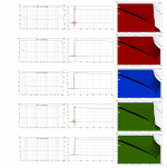
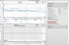
Think below is interesting loop tests run with AP192 at 48kHz (for info phase shift at low end is approximate a 2,4Hz 2. order HP).
1. is raw soundcard without any calibration.
2. is same as point 1 with IR centered commanding "Estimate IR delay".
3. is soundcard calibration and looks exactly same as point 2 except amplitude is shifted down to zero dB.
4. is with calibration file loaded.
5. is same as point 4 with IR centered commanding "Estimate IR delay".
Haha with full calibration and centered IR at HF stopband waterfall gets worst tail of them all probably because the higher order a filter gets the more it rings and with calibration everything is pure flat up to kind of brickwall cut.
Comments ?
Attachments is same (50% and full resolution)
Attachments

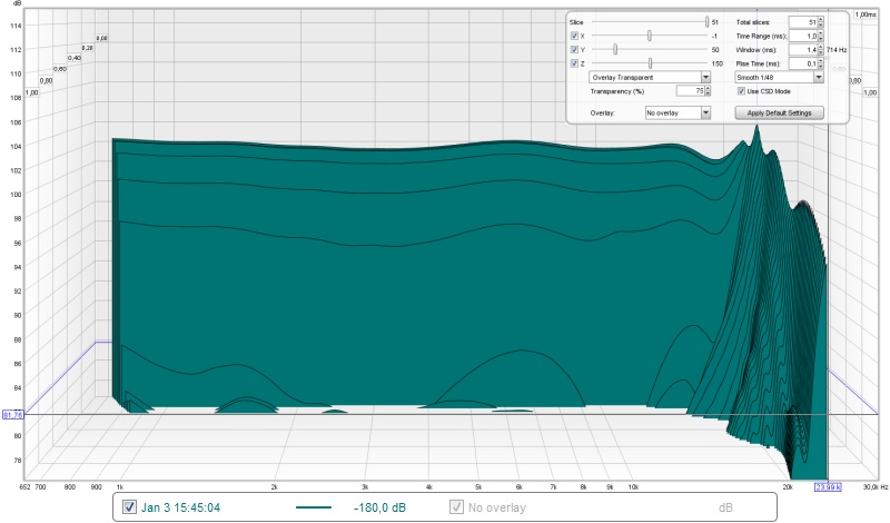
Why look at such large window settings if you want to see the ringing?
Set rise time to 0.1 and window to ~1.5 and move a bit up and down in that window time.
Time range can be 3 ms. See it ring if you move trough time of the window 1,5 to 1,6 etc? Move down in time to 0.5 ms too, You'll notice it will stop ringing and stay there at an early point.
Now start the EQ tab, set a low pass on one of the worst looking pulses. Cut it below the ringing top end, Does the IR in the preview window below look better?
In your setup, try to run a test up to 24 KHz (limit the output up high), while leaving the setup at this resolution. (your graphs show 30 KHz). Is there still a ringing visible in the IR?
Last edited:
In case this has not been posted before:
Pre- and Post Ringing of Impulse Response
Musings: Digital Interpolation Filters and Ringing
Kind regards, Mitch
Pre- and Post Ringing of Impulse Response
Musings: Digital Interpolation Filters and Ringing
Kind regards, Mitch
This is what I think I am seeing as the ringing in your IR:
Peak of ringing at 24 KHz.
Just load an EQ tab in REW, have the IR plot show in bottom window and add a low pass filter at 22 KHz, it will cut the amount of ringing in half. This isn't a proposed solution, just trying to show this is the actual cause of those ripples.
The low pass only removed some ringing and created lesser new ones at a lower frequency (the new cut-off). So it's the filter at the top end as BYRTT said. Better filters will show less ringing.
Meaning jtalden's way may be an excellent trick to get rid of it in measurements. Set it at 96 KHz, and the ringing will move up. As long as your speaker doesn't have output all the way up there the measurement will be free from the ringing coming from the sound card. At least I'd expect it to be.
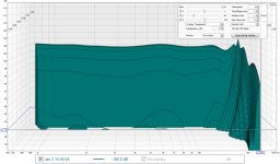
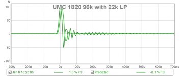
Ok, after looking at the x-32's waterfalls and impulse with a 22k Hz LP in place as shown, I decided to re-measure my three sound-card alternatives.
The x-32 is 48k max. It definitely had the messiest looking waterfall, all compared at 48k.
The UMC 404 and 1820, go to 96k.
I think 96kHz waterfalls looked much cleaner on both of these than their 48kHz rates, so jtalden's method is looking good
Waterfalls at 96k didn't change much with the addition of the 22k LP, but predicted impulse response did.
Does it make sense to add a FIR LP filter at 22kHz? (or what Hz?)
Attachments
Last edited:
Personally I don't think Holm has anything rew doesn't these days. I have also found it very much prone to crashing.
Good to know, thx.
Probably i'm a noob too but interested to learn, especially when a system band-pass acoustic gets as high in quality as your latest build then think its interesting to interpret in higher resolution to squeeze the last bit and truth out of system.
Thank you, believe me ...I'm learning a great deal from your posts !
I must be missing something in understanding the sound-card series you just posted...
It looks like either impulse is very clean, or waterfall is clean, but not both at the same time......
....with impulse being clean when "Estimate IR delay" is in..???????
This is basically the argument for a dual channel measurement system, e.g. as outlined in http://www.bodziosoftware.com.au/Single%20Channel%20Measurement%20System.pdf
Why look at such large window settings if you want to see the ringing?
Set rise time to 0.1 and window to ~1.5 and move a bit up and down in that window time.
Time range can be 3 ms. See it ring if you move trough time of the window 1,5 to 1,6 etc? Move down in time to 0.5 ms too, You'll notice it will stop ringing and stay there at an early point.
Now start the EQ tab, set a low pass on one of the worst looking pulses. Cut it below the ringing top end, Does the IR in the preview window below look better?
In your setup, try to run a test up to 24 KHz (limit the output up high), while leaving the setup at this resolution. (your graphs show 30 KHz). Is there still a ringing visible in the IR?
Imagine those are good suggestions but over my head so you welcome show new presentation
find them 5x48kHz loopback tests into below linked mdat file.OneDrive: https://1drv.ms/u/s!AqpXxWjyVD8ljW3bs7nUICMi8hB5
Last edited:
I can't seem to load an REW filter file into rePhase 2.1.0. Can someone help spot the problem?
The REW txt file contains 15 filters in the format of Post 1278. In rePhase I selected 'tools/Import REW filter settings' and then selected the .txt file. rePhase reports: 'failed to load REW Filter Settings: text export format not supported'.
I tried converting the file to xml format using MSWord but that xml file didn't load either: 'failed to load REW Filter Settings: wrong format'.
Thanks!
When you are in REW, you should save the filters with the 'Save Filter Settings to File' function. This will export filters in the correct .xml format which is supported by rePhase.
Attachments
Last edited:
I am alsp interested in a good reasonably priced mic soundcard (via usb) with phantom power. My preference would be a relatively small one.
Regards
Tascam us144 or us 122. USB
You can find them for less than 50 on ebay.
Great little units
- Home
- Design & Build
- Software Tools
- rePhase, a loudspeaker phase linearization, EQ and FIR filtering tool