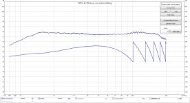
Another test with the same EQ at different frequencies, with a 512 taps impulse:
20Hz, 40Hz, 80Hz, 160Hz, 320Hz, 640Hz
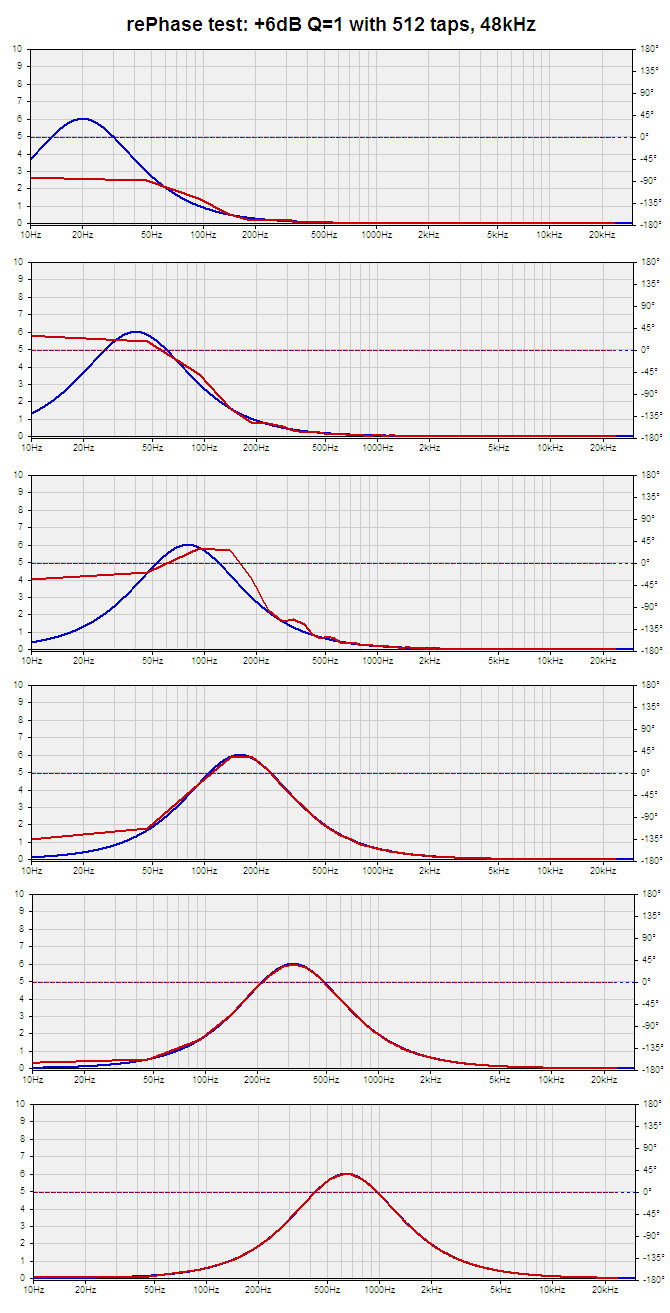
I have a question for John on this. I find it curious that as one tries to lower the cuttoff, at some point the absolute output level at the low end drops.
I wonder if this effect is part of the issue I've had with my dipole system. Do you think that trying to EQ the low end will have some hard and fast limit as to cutoff? What I see in those graphs makes me think so, at least for any specific sample rate. Looks like in my case I'm better off using a 44.1 sample rate since I need woofer dipole correction.
dlr
p.s. Sorry for the odd look. I wanted to include the image, but a QUOTE of the post dropped it.
Hi dave,
Yes, it could be the problem. Once you get low in frequency the accuracy limits can take things in weird directions. The best thing to do is to measure the UE generated filter and see what it really look like compared to what is shown in the UE screen. Then you can manipulate the target (like exaggerate the dipole boost) and remeasure the actual filter. You should be able to get something that ultimately looks like what you really want but in the UE screen it may look very different.
For example you are trying to generate a Q boost with 8dB gain and Q = 1 but it comes out looking like a Q = 0.5 with gain = 5. So try Q = 2 with gain of 11dB and see what comes out. It's manually trying to correct for the inaccuracies.
Your manual approach is pretty much the way the UE works deep down inside. You start with a measurement. That measurement can be a lot of things: the on axis response, the smoothed axial response, a spatially averaged response,..... Then, the user specifies a frequency range over which minimum phase equalization is applied to flatten the response.
I have never used UE but it looks like a very nice tool. In comparison rephase is not an integrated framework, but just a small tool to be used together with other tools (measurement software, convolution engine, etc.), that the user has to can inside its design chain.
Still, I am more confortable with manual EQ when it comes to flattening a driver.
Automated corrections can be very good (if the measurement is good and representative, that is), but this requires a lot of care.
DRC-FIR does that very well (inverted response special tricks), as well as PORC (multiple EQ with controlled Q), and I am sure UE does that quite well also.
Still... I prefer manual EQ

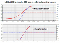
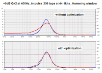
That it what rePhase does during its automatic optimization steps: it compares the target curve (in blue) and the result curve (in red, which is a fft of the generated impulse) and internally modifies the target to correct the result.For example you are trying to generate a Q boost with 8dB gain and Q = 1 but it comes out looking like a Q = 0.5 with gain = 5. So try Q = 2 with gain of 11dB and see what comes out. It's manually trying to correct for the inaccuracies.
Here is an illustration of the effect of the iterative optimization for a filter and an EQ with a window and a short number of taps:
Attachments
Last edited:
pos, I haven't tried rePhase but I hope when you look at the effect of your short FIRs, you use a MUCH larger FFT block.
ie if looking at a 512 pt FIR, you are using an FFT block of 16K or more.
Small FFT blocks hide the info between the bins. Good windowing alleviates the nasty effects but info is still hidden or fudged. Bigger FFT blocks move the problem to frequencies where it is less important or at least let you see there is a problem.
A 512 pt FIR at 48kHz has a 'resolution' of 93.75Hz so any effect it has at 20Hz is purely due to 'windowing' artifacts.
That it what rePhase does during its automatic optimization steps: it compares the target curve (in blue) and the result curve (in red, which is a fft of the generated impulse) and internally modifies the target to correct the result.
Here is an illustration of the effect of the iterative optimization for a filter and an EQ with a window and a short number of taps:
Nice. But I don't think that is exactly what dlr and I are referring to. In theory the impulse response generated by the UE should exactly produce the desired filter. But the impulse is only 8192 samples long or 5.86 Hz resolution. When actually played through the convolution engine they lose accuracy because of the required windowing which has the greatest effect on the low frequency information (windowing is akin to smoothing in the frequency domain). To improve this a longer impulse is needed (not just a longer FFT block) so that a longer window can be used and more low frequency info is retained. I don't think you can conclude what you have without making the measurment of the output of the convolution engine.
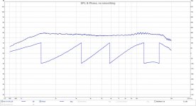
a capture of 512 taps 100 Hz +6dB eq.
sound card output after convolution,rectangular window and blackman in green.
and with the same eq with 1024 taps
sound card output after convolution,rectangular window and blackman in green.
An externally hosted image should be here but it was not working when we last tested it.
and with the same eq with 1024 taps
An externally hosted image should be here but it was not working when we last tested it.
Last edited:
a capture of 512 taps 100 Hz +6dB eq.
sound card output after convolution,rectangular window and blackman in green.
Exactly as expected.
REW delay cancellation
Hi. A question regarding phase correction. I enclose a snapshot of a nearfield measurement of a tweeter's response taken using REW. I have used the Estimate IR Delay option to, in theory, remove any delay from the IR, yet the phase still shows several complete 360 degree 'wraps'. In your opinion, is there still a delay that has not yet been removed from the IR?
Hi. A question regarding phase correction. I enclose a snapshot of a nearfield measurement of a tweeter's response taken using REW. I have used the Estimate IR Delay option to, in theory, remove any delay from the IR, yet the phase still shows several complete 360 degree 'wraps'. In your opinion, is there still a delay that has not yet been removed from the IR?
Attachments
after estimated delay,adjust sample by sample to get the correct minimum phase of requency response (i think tweeter has no electrical filter or wave guide.)
the tab on the right side below
the tab on the right side below
An externally hosted image should be here but it was not working when we last tested it.
Hi. A question regarding phase correction. I enclose a snapshot of a nearfield measurement of a tweeter's response taken using REW. I have used the Estimate IR Delay option to, in theory, remove any delay from the IR, yet the phase still shows several complete 360 degree 'wraps'. In your opinion, is there still a delay that has not yet been removed from the IR?
This is not phase correction, but calculation by REW of measurement window location, removing excess phase from displayed result.
after estimated delay,adjust sample by sample to get the correct minimum phase of requency response (i think tweeter has no electrical filter or wave guide.)
the tab on the right side below
An externally hosted image should be here but it was not working when we last tested it.
Thanks Thierry. That's got it - I didn't realise that you had the option to apply manual time offsets like that.
Edit: Also, you are right that the tweeter is being driven actively, so no filtering as such for the measurement.
Last edited:
This is not phase correction, but calculation by REW of measurement window location, removing excess phase from displayed result.
Hi Barleywater. I realise that, but before using the measured IR in order to correct the phase in the crossover, I wanted to make sure I had removed any residual delay. Manual tweaking of the time offset reduces the measured p-p phase variation to +/- 90 degrees-ish up to about 9 KHz, but it's 'worse' above that. Do you find that measurement microphones (e.g. WM61a) are not entirely trustworthy above that sort of frequency? - or I may have placed the mic too close to the tweeter..? I am minded to correct the phase in my crossover up to 9 kHz, only.
Is REW trying to find the optimum delay over the full frequency span, and maybe it's getting it a little wrong because of measurement/mic errors at the top end?
Edit: Might sub-sample adjustment in fact reduce the phase deviation further, showing it as essentially flat until it turns negative at 4.5 KHz-ish..?
Attachments
Last edited:
pos, I haven't tried rePhase but I hope when you look at the effect of your short FIRs, you use a MUCH larger FFT block.
ie if looking at a 512 pt FIR, you are using an FFT block of 16K or more.
Small FFT blocks hide the info between the bins. Good windowing alleviates the nasty effects but info is still hidden or fudged. Bigger FFT blocks move the problem to frequencies where it is less important or at least let you see there is a problem.
A 512 pt FIR at 48kHz has a 'resolution' of 93.75Hz so any effect it has at 20Hz is purely due to 'windowing' artifacts.
Hi kgrlee,
rePhase internally works on an impulse that is twice the size of the smallest or equal power of 2 from the requested length (for exemple 6144 or 8192 => 16384, 8193 => 32768).
This is done to let the auto centering algorithm do its job. Longer ifft for do not give to better precision for the final impulse
You are absolutely right for the final fft though (the one used for the result visualization):
Current version of rePhase is using the same length for this final operation, and some info is hidden.
I will change this in a next version, but I will have to rework some internal stuff for that (the optimization is based on that final fft, so it helps if is is the same length as the one used for the generation, but it can be changed).
I usually use larger taps then the ones showed here, so this issue was not showing too much.
This has no impact on the final result though, as when viewing the generated impulse in HOLM for example you get all the info that was missing in rePhase visualization.
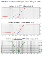
Here is a comparison of the same filter with only 256 taps and a rectangular window (to make ripples more apparent) with first the same length for the final fft as the one used for the ifft (current rePhase behavior), second a larger fft (due for a next release
), and third both impulses loaded in HOLM, showing the same behavior.Thank you for pointing out this visualization issue
Attachments
Too late to edit my previous post. I was going to add:
I still haven't got my head around phase vs. delay when it comes to 'correction'. If there's a phase deviation of >360 degrees (which constitutes a delay..?) I'm assuming that it's not possible to correct it by phase only, and maintain time domain coherency of a transient - which I had thought was the main aim of the exercise, apart from matching drivers' phase in the crossover region.
Do real world drivers exhibit a phase characteristic and also a delay characteristic i.e. a pulse can be set in motion that doesn't emerge at the diaphragm until a fixed propagation delay has passed?
Is there an upper frequency limit to phase correction?
Nice. But I don't think that is exactly what dlr and I are referring to. In theory the impulse response generated by the UE should exactly produce the desired filter. But the impulse is only 8192 samples long or 5.86 Hz resolution. When actually played through the convolution engine they lose accuracy because of the required windowing which has the greatest effect on the low frequency information (windowing is akin to smoothing in the frequency domain). To improve this a longer impulse is needed (not just a longer FFT block) so that a longer window can be used and more low frequency info is retained. I don't think you can conclude what you have without making the measurment of the output of the convolution engine.
I think rePhase does precisely what you were talking about:
The best thing to do is to measure the UE generated filter and see what it really look like compared to what is shown in the UE screen. Then you can manipulate the target (like exaggerate the dipole boost) and remeasure the actual filter. You should be able to get something that ultimately looks like what you really want but in the UE screen it may look very different.
This is what rePhase does (or at least tries to, it could certainly be improved) automatically in its iterations steps: internally modify the target curve so that the result curve (accounting for the number of taps, the centering, and the window function) fit the original target curve better, by comparing the two and doing compensations.
Hi CopperTop,
First, maybe you should use some filter on your tweeter to avoid destroying it during measurements!
HOLM has the ability to filter the measurement signal (using linear phase brickwall filters), so you can measure without messing up the phase with an IIR filter (though this can be taken into account as well).
HOLM is also very good for phase analysis, and let you choose the offset of the impulse very easily.
When choosing the offset of the impulse you should look for the first peak, which should also be the biggest and be positive.
You can play with polarity to get that right, and if your filtering is phase coherent and the delay is right between drivers (or if you are measuring a unique driver like you are doing here), you should get a clear positive peak.
If you place the offset right on the top of that peak you will have a phase curve that ends up precisely at 0° at the nyquist frequency, and you should be able to "see" the theoretical behavior of your filters below that: phase rising slowly at the low part of the band for your tweeter, or faster phase shifts at each crossover points if you are measuring a multiway speaker with IIR crossovers.
To be complete, I should add that having a phase that ends up at 0° at the nyquist freq is not always what you should be looking for, and any IIR crossover (or natural roll off) will introduce a phase shift that will still have some impact at the nyquist frequency (the higher the order and the frequency, the more shift you will still have).
So when adjusting the offset you should look for a phase that asymptotically "goes" to 0° for an infinite frequency...
Last edited:
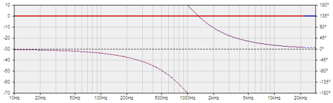
To illustrate that "0° at nysquist" thing here is the simulation of a LR 24dB/oct filter at 1khz.
You can see that a the nyquist freq (22khz) there still is some phase shift that remain.
It is even still there at 30khz, and will slowly and asymptotically reduce as frequency rises.
You can see that a the nyquist freq (22khz) there still is some phase shift that remain.
It is even still there at 30khz, and will slowly and asymptotically reduce as frequency rises.
Attachments
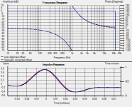
Now if you load that impulse in HOLM and let it automatically detect the offset (highest/first/positive peak), it will set the phase at 0° at the nyquist frequency (blue curve).
But if you manually adjust the offset (+0.041 sample here, using the offset given by rePhase when generating the impulse) you will be able to get the phase where it is supposed to be at the nyquist freq (red curve, around 8° remaining).
This is no big deal (nothing will change for the range bellow), but is worth mentioning I think...
Attachments
So when adjusting the offset you should look for a phase that asymptotically "goes" to 0° for an infinite frequency...
I would not agree with that statement. It assumed that the response of what ever is being looked at remains flat to infinity. But all drivers, tweeters, etc, are band pass devices and will have some form of LP filter at their upper frequency limits. This will result in the phase approaching some non zero asymptot as frequency goes to infinity. For example, if the tweeter rolls off 2nd order at 30 K Hz the phase would asymptot to -90 degrees. When you are doing phase correction you want to start with the minimum phase of the driver and maybe the delay due to relative offset to other drivers in the speaker.
- Home
- Design & Build
- Software Tools
- rePhase, a loudspeaker phase linearization, EQ and FIR filtering tool