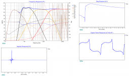
Good here the four band passes into XSim linked to four individual parallel coupled drivers, blue traces is sum.
First plots the four raw frd responses, second plots the four rephrase corrected files, third plots same a second but with MW lowered -3dB.
Looks as slopes for W and MW need more trim care.
First plots the four raw frd responses, second plots the four rephrase corrected files, third plots same a second but with MW lowered -3dB.
Looks as slopes for W and MW need more trim care.
Attachments


Good here the four band passes into XSim linked to four individual parallel coupled drivers, blue traces is sum.
First plots the four raw frd responses, second plots the four rephrase corrected files, third plots same a second but with MW lowered -3dB.
Looks as slopes for W and MW need more trim care.
Thanks a lot BYRTT for the analysis.
Yeah, i will do the level match using Jriver plugins as you had suggested.
I will work on better blending of the XXLS and W22s
Do the phase and driver delays appear ok?
Thanks a lot BYRTT for the analysis.
Yeah, i will do the level match using Jriver plugins as you had suggested.
I will work on better blending of the XXLS and W22s
Do the phase and driver delays appear ok?
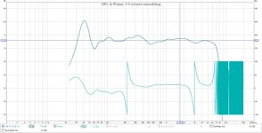
Based sense from previous posts this is your first attempt into DSP and Rephase this is very good work, system phase (blue) varies in bandwidth around +/- 20º and in finale system you still have live delay and spl switches to tweak on, and also a system EQ to form a house curve could be added there.
Did look closer in Rephase files and some error seems MW has LR8 HP and W has LR4 LP filter, will try edit and come with two new plots where W/MW XO with LR4 and or LR8 slopes.
Last edited:
Hilbert's transform i guess .. not so accurate.
John K. told about that here:
http://www.diyaudio.com/forums/mult...e-linearization-eq-fir-filtering-tool-12.html
The critical part of minimum phase extraction has been described in John’s post #120.
The FFT/IFFT method is inaccurate with the error increasing towards low and high frequency limits, therefore, if this is what REW implements, then the minimum-phase will be quite inaccurate.
The integral approach offers the most accurate minimum-phase extraction and is supposed to be calculated from 0Hz to infinity Hz.
In real life, we only need phase response between some frequency extremes (high and low frequency limits of the REW display screen), and this allows us to extract the minimum-phase within these limits by actually calculating it over much wider frequency limits first.
The wider frequency limits that must be used for calculating the minimum-phase are typically one decade below the low frequency and one decade above the high frequency displayed on the screen.
Say for instance, your REW screen limits are 10Hz – 20000Hz. Then you need to calculate minimum phase integral from 1Hz – 200000Hz and then discard the phase 1Hz – 10Hz and 20000Hz – 200000Hz, as it will be inaccurate.
It is obvious, that in order to extract phase from amplitude over the wider frequency range, you must have SPL specified over the wider frequency range in the first place.
So the issues here is – what is the SPL outside the screen frequency limits?. In our example above, you need to somehow define SPL 1Hz-10Hz and 20000Hz – 200000Hz. I could not find any information on how this is done in REW.
Understanding the mechanism of minimum-phase extraction is very important, as it will tell you if you have your minimum-phase calculated accurately or with significant errors.
One is good to use, the other is not.
Hi BYRTT,
Yes that was an error on my part. I intended to use LR8 symmetrically for XO between the W(XXLS) and MW(2x parallel W22). Note that the XO is at 60Hz, but i also wanted to shelve the drivers to overlap over 60-100Hz range.
One thing i want to mention is that the 12" XXLS are mounted on the sides of the speakers where the W22 are on the front baffle.
I suppose REW is interpolating frequency response .(maybe 96K or 192K)
At least,4 samples by period are needed to process a Hilbert Transform.(90° phase shift).
So 96K seems to be ok for 24KHz upper limit.
Is it really important to obtain an accurate HT (graphically) at 20KHz...
As the purpose of this information is to display excess group delay (excess phase).
It is not used to calculate/extract impulse response in real life.
Last edited:
As to the phase alignment between sub and full range box,I usually do
it without the IR as the long wavelengths "smear" the detection of the spike on finding initial time as the peak level.I always apply the full range box first to remove the time of flight,and along with the sub(still use this flight time and compensate the time difference in the wrap phase window,that is the same phase slope)
IF using rephase,just select the same topology type,slope and center frequence point of HP/LP filter.No concern about the time/phase alignment.
Min phase or excess phase is not so important for me because the free field data I obtain will be in the 6~8m distance by the ground measurement.The EQ applies to it(in the free field) and then nothing will do you a favour especially in the room.In all reflection enviroments,very few chances you get the min phase,and EQ will be only valid at the mic location it's placed.
Best Regards
I am ready to try out the filters on Jriver and measure the response.
I created the jriver convolution engine config file, however i am not sure about the channel mapping
cfg file refers to output channel as 0,1,2,3.....
Jriver refers to output channels as Left, Right, Center, sub....
Motu interface Analog outputs are labeled 0,1,2,3....
How to confirm the filter to output channel mapping. I will surely fry the tweeter if i send my filtered woofer channel to it through ncore400
Also, what should be the order in Jriver between convolution (Filters) and parameter EQ (delay and level), which should be listed first?
I am ready to try out the filters on Jriver and measure the response.
I created the jriver convolution engine config file, however i am not sure about the channel mapping
cfg file refers to output channel as 0,1,2,3.....
Jriver refers to output channels as Left, Right, Center, sub....
Motu interface Analog outputs are labeled 0,1,2,3....
How to confirm the filter to output channel mapping. I will surely fry the tweeter if i send my filtered woofer channel to it through ncore400
Also, what should be the order in Jriver between convolution (Filters) and parameter EQ (delay and level), which should be listed first?
Is your a 4 way active system, right? In this case you should use the "2 channel in a 7.1 container" setting. With this setting the ways are named in a different way: Left, right, center, sub, Rear left, rear right, surround left, surround right. I have connected the subs to left and right, the low voices to center and sub, the mid voices to RL and RR and finally the high voices to SL and SR.
The corresponding config text is the following
48000 8 8 0
0 0 0 0 0 0 0 0
0 0 0 0 0 0 0 0
D:\FIR 18.1 48k\LPL-R1710.wav
0
0.0
0.0
D:\FIR 18.1 48k\LPL-R1710.wav
1
1.0
1.0
D:\FIR 18.1 48k\BP1L1710.wav
0
0.0
2.0
D:\FIR 18.1 48k\BP1R1710.wav
1
1.0
3.0
D:\FIR 18.1 48k\BP2L1710.wav
0
0.0
4.0
D:\FIR 18.1 48k\BP2R1710.wav
1
1.0
5.0
D:\FIR 18.1 48k\HPL1710.wav
0
0.0
6.0
D:\FIR 18.1 48k\HPR1710.wav
1
1.0
7.0
You can put the PEQ both before and after convolver. As opposite, in order to perform DRC you need of a second convolution and in this case you must put the convolver VST BEFORE the convolver integrated in Jriver
An interesting tip for convolver,
to redirecting all channels to 1 (or more sub) for example:
...
c:\impulse sub.wav
0
1.0 2.0 3.0 4.0 5.0 (channels input)
1.0 (sub channel out for ex)
Attenuation has to be adjusted.
in one line,convolver is processing all channel to one (or more).
it's working in the other way too.(1 channel input---->x channels output).
An externally hosted image should be here but it was not working when we last tested it.
Last edited:
Is your a 4 way active system, right? In this case you should use the "2 channel in a 7.1 container" setting.
I think the standard configure txt for 2 inputs -> 8 outputs is like this :
( maybe both works ? )
48000 2 8 0
0 0
0 0 0 0 0 0 0 0
I think the standard configure txt for 2 inputs -> 8 outputs is like this :
( maybe both works ? )
48000 2 8 0
0 0
0 0 0 0 0 0 0 0
Hi jmbee,
my setting (2 channel in a 7.1 container) works well. It was suggested to me by Mwillems of the JRiver's forum.
Regarding the config text file I've seen in the past that even with some errors inside (e.g invalid address of the directory where the files are) it continues to works (provided that the config file was in the same directory of the FIR filters)
first set of results after measurements and tweaks.
Some more tweaks remain, but they sound incredible
http://www.diyaudio.com/forums/multi-way/272781-advice-needed-4-way-loudspeaker-34.html#post4631961
Please review, comment.
Some more tweaks remain, but they sound incredible
http://www.diyaudio.com/forums/multi-way/272781-advice-needed-4-way-loudspeaker-34.html#post4631961
Please review, comment.
")
- Home
- Design & Build
- Software Tools
- rePhase, a loudspeaker phase linearization, EQ and FIR filtering tool