Complementary means the same on either side. The low pass and the high pass are exact opposites of each other.Sorry for needing to be spoon-fed, but I'm not sure what the complementary thing means in rephase.
If you have a protection cap or woofer that rolls off naturally near the crossover or tweeter that rolls off below the crossover your acoustic slopes will be a combination of the electrical filtering and acoustic filters. You may have complementary electrical filters but not complementary acoustic slopes.
You can check by using rephase to generate the electrical slope you are targeting and use that in REW as an overlay or in AllSPL to visually see if they are the same.
As per now this is presicely what I feel happened, only oppositeI can't wrap my head around how I can add delay to one of two drivers that sums in phase without messing up the phase coherency
You can use the alignment tool in REW to see what delay is needed to align the phase at the crossover point which is normally the aim when using named crossover filters.
You can see in the step response or spectrogram how well your drivers are aligned in time.
It seems like you have a short gate set as the gate smoothing is coming in quite high. This will make it difficult to see much detail as frequency goes down.
Using a single axis measurement to judge a crossover is not a great way to do things and you will get better timing measurements using your analogue mic than using an acoustic timing reference. You can use the UMIK to calibrate the ECM against if it is not calibrated.
I would suggest having a look at these documents guides to get a better idea on how to measure a speaker to allow it to be re-designed.
https://kimmosaunisto.net/Software/VituixCAD/VituixCAD_Measurement_REW.pdf
How to make quasi-anechoic speaker measurements/spinoramas with REW and VituixCAD | Audio Science Review (ASR) Forum
rephase is a great compliment to a design tool like Vituix but not a replacement.
Thank you for explaining. I think you are absolutely correct, I need to take more time and study design and measurement basics. I have parts on the way for building new speakers so I could really benefit from this. That was the whole reason for making my present speakers active in the first place, to gain some experience. Rephase seems like a really nice software in this process but I need more practice
In regards to gate time I set it to 3.5ms due to my room beeing quite small. If I have understood things correctly that will yield acuracy down to about 285Hz. Attached pic of IR from that measurement from my last post
What you say about complementary off course makes sense and I get that electric roll off is not necessarily the same as acoustic roll off. Good advice on using REW to check if the slopes match. I just import the IR I made in rephase, correct? Using spectrogram in REW calls for more than one measurement I would think? On axis not beeing enough I mean
Also I have mulled over the issue I had with timing/delay and maybe I over-complicate the ide? Is it perhaps just the order of execution? If I add delay before adding XO slopes, the delay and therefore phase will be correctly tuned when tuning XO after delay is added.
Attachments
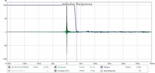
You won't get accuracy at 285Hz with a 3.5ms gate. That is considered to be the minimum frequency for the data to be in any way valid but the problem is the smoothing effect it has on the response.
At 285 Hz it is like having 1/1 octave smoothing being applied with the smoothing getting less as frequency rises until you get to a point where there is virtually no difference.
Here is an old B&K document that still has some good explanations
https://www.bksv.com/media/doc/17-196.pdf
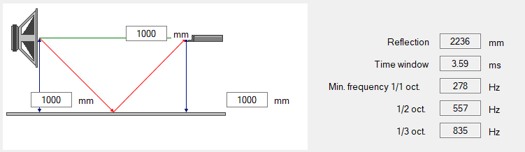
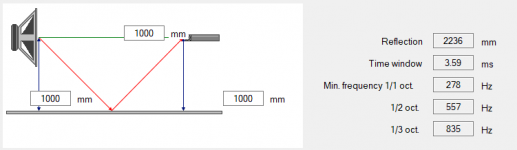
Vituix's calculator can show the frequencies of different effects based on the reflection time
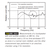
Here is a comparison from Floyd Toole's second edition book showing an anechoic vs 10ms gate. You can see that at 500Hz it is virtually the same but below that it is not that accurate. At 3.5ms the same effect will occur higher in frequency.

At 285 Hz it is like having 1/1 octave smoothing being applied with the smoothing getting less as frequency rises until you get to a point where there is virtually no difference.
Here is an old B&K document that still has some good explanations
https://www.bksv.com/media/doc/17-196.pdf
Vituix's calculator can show the frequencies of different effects based on the reflection time
Here is a comparison from Floyd Toole's second edition book showing an anechoic vs 10ms gate. You can see that at 500Hz it is virtually the same but below that it is not that accurate. At 3.5ms the same effect will occur higher in frequency.
Attachments
Last edited:
Yes import the crossover impulse and rescale the level to match your speaker measurement.Good advice on using REW to check if the slopes match. I just import the IR I made in rephase, correct?
It will only work on one measurement, you might be thinking of a polar plot.Using spectrogram in REW calls for more than one measurement I would think? On axis not beeing enough I mean
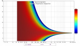
Here's an old image showing the idea, it is a time vs frequency graph that makes it easy to see where in time the frequencies are happening. This is a rephase generated Dirac Pulse.
Attachments
Thanks for all this info, it's all both eye-opening and confusing at the same time. I get the notion that it's not possible to do reliable measurements in what spaces I have available and outdoor is not a option for me due to weather, noise, close neighbours etc. The B&K paper mentioned a warehouse witch is just impossible, but the VituixCAD tutorial mentioned one place that gating should be 3-5ms. So I'm not sure what to make of all this. Best I have available is my garage witch is a 50m2 space. Also there was a lot of talk about tone bursts and burst lenght in the B&K paper, but I take it this has to do with their hardware and is not aplicable when using REW?
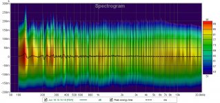
You are correct, I was thinking about polar plots. I think I understand the spectrogram example you posted and tried generating one from my measurement, not sure what to make of it though...
You are correct, I was thinking about polar plots. I think I understand the spectrogram example you posted and tried generating one from my measurement, not sure what to make of it though...
Attachments
It may seem confusing but you can get reasonable measurements indoors without needing a warehouse. The first thing is to get as long of a reflection free gate as possible. Putting the speaker halfway between the floor and ceiling is usually the best you can do as they tend to be the closest surfaces.
The longer the gate the lower you can rely on it being accurate. Then you can use nearfield measurements and simulate baffle diffraction for the lowest frequencies which is usually pretty accurate for conventional speakers.
The nearfield is only valid up to a certain frequency and beyond that it becomes unreliable just like the gate. The area between from 200Hz to 800Hz is where there can be insufficient resolution to fully describe the speakers output if the gate time isn't long enough as shown in the Toole graph.
Have a look at this Arta Application note for more information
https://www.artalabs.hr/AppNotes/AN4-FreeField-Rev03eng.pdf
Don't worry about the B&K signal processing as things have moved on since 1975 but the basic principles are still the same.
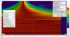
As for the spectrogram you have to change the settings to get anything useful and some of them will depend on the signal level etc.
I have attached a screenshot below that might help get you something more useful.
The longer the gate the lower you can rely on it being accurate. Then you can use nearfield measurements and simulate baffle diffraction for the lowest frequencies which is usually pretty accurate for conventional speakers.
The nearfield is only valid up to a certain frequency and beyond that it becomes unreliable just like the gate. The area between from 200Hz to 800Hz is where there can be insufficient resolution to fully describe the speakers output if the gate time isn't long enough as shown in the Toole graph.
Have a look at this Arta Application note for more information
https://www.artalabs.hr/AppNotes/AN4-FreeField-Rev03eng.pdf
Don't worry about the B&K signal processing as things have moved on since 1975 but the basic principles are still the same.
As for the spectrogram you have to change the settings to get anything useful and some of them will depend on the signal level etc.
I have attached a screenshot below that might help get you something more useful.
Attachments
Ok, I think I'm starting to see some of the "picture" here so thanks for taking time explaining!
I was going to respond to what you said about far field and near field measurement combined. I have tried this a few times before but I struggle with the math on how to scale the responses for splicing them. After skimming the ARTA paper I see there is good info on that so I need to study it and have a go at the procedure. Sadly math has always been hard for me so it takes some time for it to make sense.
Ill try againg on the spectrogram as well

I have a question about rephase if it's alright. Forgot a moment that this is a thread about rephase
When generating a filter IR in say wav, when and why do you use mono or stereo? Is it when you use one file for both L and R channels? And mono if you make for let's say only L? Perhaps a bit of a dumb question but I want to know and not asume things
When generating a filter IR in say wav, when and why do you use mono or stereo? Is it when you use one file for both L and R channels? And mono if you make for let's say only L? Perhaps a bit of a dumb question but I want to know and not asume things
The dotted black line should be straight at 0 but you have some swings either way possibly the result to using phase EQ. An ideal minimum phase speaker response would be straight with a bend to the right at the low frequency roll off point.
Yes stereo will just put the same filter in both channels mono would be be for separate channel filters.
Yes stereo will just put the same filter in both channels mono would be be for separate channel filters.
The dotted black line should be straight at 0 but you have some swings either way possibly the result to using phase EQ.
Does this have anything to do with the delay/latency as a result of using FIR filters? I was under the impression eq'ing phase to flat was a good thing, not counting the lantency
Last edited:
It has nothing to do with latency. If you use phase EQ that can add pre-ringing to the impulse response which will show up on the left side of that graph. The dotted line is the peak energy curve and shows that at some points the peak energy is ahead of the main impulse peak time.
The problem with equalizing phase to a flat line is it doesn't help you to understand where that phase came from or whether you should try and change it.
In a speaker with linear phase crossover filters there should really be no need to use phase EQ.
The problem with equalizing phase to a flat line is it doesn't help you to understand where that phase came from or whether you should try and change it.
In a speaker with linear phase crossover filters there should really be no need to use phase EQ.
Got it, I think. So in other words a passive crossover speaker would not show this behaviour on the left sideIt has nothing to do with latency. If you use phase EQ that can add pre-ringing to the impulse response which will show up on the left side of that graph. The dotted line is the peak energy curve and shows that at some points the peak energy is ahead of the main impulse peak time.
I would think you are correct since my measurement wich EQ is based on is not very accurate and more than likely contain more than just direct soundIt looks like the phase has been corrected for the direct sound plus it's reflections.
I don't think that's a good idea.
I'm am currently deep in the reading material kindly provided here and will continue this until I feel more confident about doing new measurements
The difference between properly implemented LR and odd order Butt should be more subtle than that: we are talking about a 3dB difference in the power response at the crossover frequency.
Chances are that if you replace your current 3rd Order Butts + inverse allpass with linear phase 4th order LR you would probably get a pretty similar result.
In any case, the difference you get between a LR and odd order Butt is not linked to the apparent early rolloff of one compared to the other: the difference is solely in the off axis behavior.
So 2 months later .... I finally got it !!!
So I left all my LRs except one....
So my midbass to midrange crossover, on the midrange I kept the linear phase LR2@300hz on the midbass I did the BW18 with the all pass..... this is what I got..
It does sound very much the same except!!!! Wait for it.......
I NO longer have acoustical cancellations between the mid and midbass on the left side (which is the farthest off axis to my seat) those two drivers would be out of phase with each other only at 265hz with a fairly sharp Q notch, (midrange on dash , midbass in Kick Panel on floor)
I was using BWs on both HP and LP , i needed to just do the BW on the LP side.
Now I get the 90-180 is still 90..... no wonder why that fixed that cancellation without any adverse affects to the crossover on the HP going into the delicate midrange and it’s crossover with the HF driver......
Seems all the deep very high Q notches between mid and midbass are so much more smoother now..... AND the crossover region lost a hollowish sound and is now punchy at 300hz, where before it was very dry sounding almost spitty.
Now this is a gem of a car audio hack that is my secret weapon now
I love it
- Home
- Design & Build
- Software Tools
- rePhase, a loudspeaker phase linearization, EQ and FIR filtering tool