An issue like the crosstalk between channels could be confirmed or excluded with a simple experiment. Make a measurement with the loopback timing on and one with it off, compare them and see if there are any differences then decide for yourself if it is an issue.
The loopback will remove electronic propagation delays and give a consistent baseline but when you move the mic from side to side for the averages the impulses will still need to be realigned to some extent anyway.
The loopback will remove electronic propagation delays and give a consistent baseline but when you move the mic from side to side for the averages the impulses will still need to be realigned to some extent anyway.
You should verify your settings, the impulses looks flabby
So,
What do you think about Lake control devices ? (raised cosine)
Seems to face to an arrogant person.
show your knowledge/measurement in relation with this thread.
Last edited:
My joke has hurt you... i'm sorry, it was stupid.
But my test room and all my audio stuff are dismounted and stocked.
So as you can imagine my arguments will be severely impacted by uncontrolled factors as the lack of everything.
You perhaps forget to demand my measurements when i've posted my message, it's really a shame to be so shy !
But my test room and all my audio stuff are dismounted and stocked.
So as you can imagine my arguments will be severely impacted by uncontrolled factors as the lack of everything.
You perhaps forget to demand my measurements when i've posted my message, it's really a shame to be so shy !
OK OK then, I'll leave it as is
...
 .....because Joshcpct is right in its genius button.
Mops1337,
Would you share some more info on physical speaker, measurement point in space and target goal you want to achieve there.
In general its so that sound waves starts as minimum phase so if they smoothed out using minimum phase (IIR) correction then phase will follow and smooth out too, so as for your curve that have ripple in amplitude domain then there should also be ripple in phase domain, problem is in acoustic domain to have good trust full measurement to base correction and the training and knowledge not to try correct into trouble areas that is impossible to repair in electric domain.
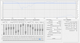
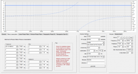
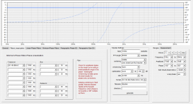
Could be wrong but it looks you try to linearize excess phase from a IIR XO point with 13x Phase EQ on "Paragraphic Phase EQ" tab which is doable but difficult job, instead use "Filters Linearization" tab for that job, below first attachment is yours phase settings set by its own where second is close to same using smoother 4th order phase correction at the other tab and third is example a 8th order correction because it looks your phase wraps around 720º in that area.
Would you share some more info on physical speaker, measurement point in space and target goal you want to achieve there.
In general its so that sound waves starts as minimum phase so if they smoothed out using minimum phase (IIR) correction then phase will follow and smooth out too, so as for your curve that have ripple in amplitude domain then there should also be ripple in phase domain, problem is in acoustic domain to have good trust full measurement to base correction and the training and knowledge not to try correct into trouble areas that is impossible to repair in electric domain.
Could be wrong but it looks you try to linearize excess phase from a IIR XO point with 13x Phase EQ on "Paragraphic Phase EQ" tab which is doable but difficult job, instead use "Filters Linearization" tab for that job, below first attachment is yours phase settings set by its own where second is close to same using smoother 4th order phase correction at the other tab and third is example a 8th order correction because it looks your phase wraps around 720º in that area.
Attachments
@BYRTT : exactly!
I made good experience when making the pure minphase-amplitude EQing in a first step to have a reasonable curve that sounds good, leaving the phase alone, till the magnitude verifies to sound just right.
Then, second instance, I measure the whole speaker as bunch, on listening position, and apply the REW frequency-window very tight, to 3 cycles for example. That's in most cases sufficient for 2-way or not so steep 3-way setups to fit into the window. That result is smooth due to EQ earlier and the smoothing side-effect of the windowing, leaves smaller risk for overcorrection.
If it may not fit, you can always run multiple instances of correcting the correction, each time with 3 cycles. That pulls the response tail closer and closer to the peak, without risking prering in most cases.
At the end, I always check that the total phase does not come earlier than the generated minphase at any point, rather always sliiiightly later.
So in a nutshell, excess-phase correction can be done in a very very short window, other than the amplitude.
The 3-way studio monitors I'm building are almost finished. I bought an OpenDRC-DA8 to filter them.
I was thinking using 500Hz and 3800Hz as crossover frequencies. We can do measurements outside with an EMM-6 on a Roland UA-25. The speaker should have a low latency of let's say <10ms if possible.
What would be the best approach?
I was thinking using 500Hz and 3800Hz as crossover frequencies. We can do measurements outside with an EMM-6 on a Roland UA-25. The speaker should have a low latency of let's say <10ms if possible.
What would be the best approach?
Last edited:
Hello WalterPPK,
You can build a minimum-phase crossover in FIR and get almost no delay out of a direct convolution box like the openDRC. You can also use its IIR capabilities.
You can latter choose to replace minimum-phase crossovers with linear-phase ones (or linearize the phase of IIR filters) at the cost of some additional delay.
The 3800Hz crossover will not be a problem in term of delay, but the 500Hz one might be. A gross approximation would be around 10ms of delay for a linear-phase 24dB/oct 500Hz acoustical target, and 20ms for a 48dB/oct one.
Ask 10 people and you'll get ten different answers . I happen to agree with John Kreskovsky's post 419.
. I happen to agree with John Kreskovsky's post 419. Thanks Pos for your quick answer. Is there much difference in sound between a min-phase and lin-phase crossover?
I happen to agree with John Kreskovsky's post 419.
http://www.diyaudio.com/forums/mult...ion-eq-fir-filtering-tool-42.html#post3502798
One thing for sure: with 10ms of allowed delay there is not enough time to address the system's high pass as described in Bohdan's experiment.
The philosophy about how relevant the phase is, was discussed very often.
I think we can agree that theyre subtle in comparison to tonal coloration of amplitude.
BUT, it cant hurt to do things properly
Really? You do this on the cost of pre-ringing
I studiet prering with simulation and I can tell you, its worse than phase shifts. I studied the roots and how to avoid this in reality.
I can give you a small recommendation:
1. In the range of XO where the crossover frequency lambda/4 is smaller than the offset between the divided drivers center-center: it doesn't matter.
2. If the offset is bigger: your audible-part-of-prering should not be longer than the TOF duration of the first main room-reflection peak in your ETC.
Means:
check ETC: first reflection peak after main impulse comes for example after 3ms. Audible prering shouldn't be longer than 3ms.
What is audible?
Well looking at distortion, at least 40dB below the impulse peak. 60 is even better, but a bit hard.
How to do this?
Simple make your fir max 6ms.
Advanced: create any filter you like, set the peak 3ms after start, and see how good your phase reaches the target. If it doesn't work, accept the remaining phase-shift
-OR-
choose a less steep filter (less phase shift)
Why? Because driver-to-driver offset bigger than lambda/4 will create preringing off-axis, radiated to your room (though canceled out on axis) and that reflection will bounce to your ear and arrive (in worst case) even before the speaker "starts playin music on axis" - which you will hear as rining (smeared impulses, background noise).
If it arrives later (therefore ETC analysis), itll merge into the diffuse-echo and be masked (inaudible).
cheers
Josh
Mops1337,
Would you share some more info on physical speaker, measurement point in space and target goal you want to achieve there.
In general its so that sound waves starts as minimum phase so if they smoothed out using minimum phase (IIR) correction then phase will follow and smooth out too, so as for your curve that have ripple in amplitude domain then there should also be ripple in phase domain, problem is in acoustic domain to have good trust full measurement to base correction and the training and knowledge not to try correct into trouble areas that is impossible to repair in electric domain.
Could be wrong but it looks you try to linearize excess phase from a IIR XO point with 13x Phase EQ on "Paragraphic Phase EQ" tab which is doable but difficult job, instead use "Filters Linearization" tab for that job, below first attachment is yours phase settings set by its own where second is close to same using smoother 4th order phase correction at the other tab and third is example a 8th order correction because it looks your phase wraps around 720º in that area.
Thank you for your response.
my Setup:
2x XTZ 99.25 Speaker
1x XTZ 10.17 Sub
Pioneer VSX 2020 Amplifier
MiniDSP 2x4HD
My measurement environment
I am sitting in a corner of the triangle created by my two front speakers and me. Sub is on the right side near my right speaker. As a DSP i use a MiniDSP 2x4 HD. My microphone is about 4m away from each speaker.
My goal
For measurements i use the MiniDSP UMIK-1, and REW/rephase as software.
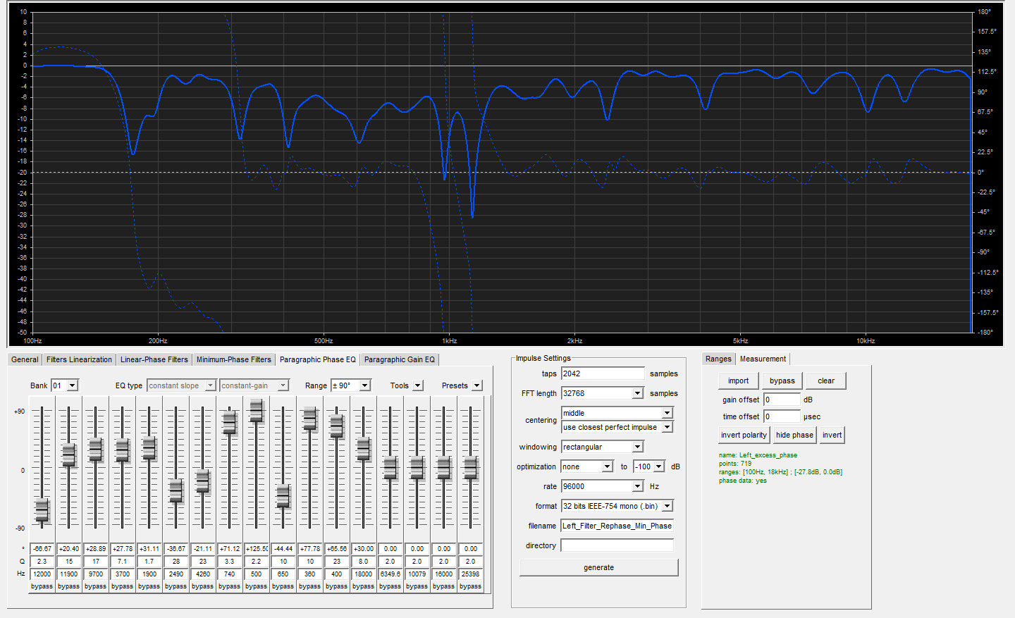
For the last years i just used REWs automatic EQ tool, which gave me good results in past time. But now i want to try something new with the 2x4HD and its FIR Filters. The DSP has 2042 Taps per Channel, and a sample rate of 96k. So i dont have the possibility to create linear phase crossovers, because i dont have enough taps. The crossover at my front speakers is a IIR Filter LR 24dB/Oct at 90Hz. My goal is to get a system which has a very small phase response
What i tried so far
I tried to follow the tutorial i found here in the forum: Dropbox - REW_rePhase_tuto.pdf
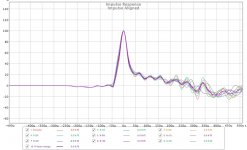
I did 9 measurements per Channel, timealigned them and created a vector average of each channel with a FDW of 15 cycles. For the measurement i used a Sweep from 150Hz to 18kHz. I did the measurement around my head with the parallelepiped method. Is it correct that i sit in place and hold the mic while the measurement? Or should i use a microphone stand?
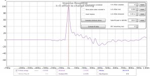
With that vector average i created some EQ filters and did the excess phase. It was my goal to bring the excess phase down to zero. Is this usefull? My result(just the left speaker) is what you see in the attachment.
Is this method correct? Maybe you can give me some advice what i can do better? Maybe you have a method which gives me better results?
The loopback will remove electronic propagation delays and give a consistent baseline but when you move the mic from side to side for the averages the impulses will still need to be realigned to some extent anyway.
Ok. Still, after reading this whole thread 230 pages, I am not exactly sure how to make the time alignment correctly in REW for importing into rePhase. Maybe I am stupid, or maybe I should stop reading this things in the middle of the night
I have the timing reference channel wired, and in use, in REW.
To "realign the impulses", which exact inputfield (name of the field) in REW do I modify? And I should enter the time where the positive peak peaks, in my case (with timing reference channel engaged)?
The new "time align"-function in REW. Does it override the loopback-timing, if I press that button?
To get the offset found by the the loopback-timing into the exported measurement as text, do I need to enter it manually in some input-field in REW? Or does it get in there automatically, if loopback is engaged in the preferences?
What use do I have of the timing reference channel and/or the "time align"-function, if I still must "realign the impulses" manually?
(bare with me, I am new to this)
Last edited:
My plan is to first try to do a "pseudo-anechoic" speaker correction / active crossover (using that kind of measuring techniques), and then as a second step try the average room correction from the tutorial, on top of this.
How would this best be done in rePhase? Keep it in separate banks but in the same output impulse, or in separate setting files and separate impulses?
(I can chain several FIR-blocks in my dsp)
My plan for the speaker correction is to keep the minimum-phase correction in one FIR-block, and the filter-linearization in a separate FIR-block (and separate rePhase-project). In that way I can turn on/off the linearization with my program selector knob in "runtime".
Last edited:
@ Mops: sounds good, in general that's all fine
@ Rajapruk: chaining works for convenient drafting as first instance, but the delay and the noisefloor of bit-rounding is doubling/increasing. So I wouldn't keep that for listening, only for measure test.
reg. the loopback, that's useless for speakers, as its just taking the few milliseconds of the loop out of the measure.
Your measurement contains digital buffer, delay of elec. devices, time of travel through air to the microphone. All that is linear on all frequencies and therefor irrelevant. The delay detector (REWs IR peak finder) eliminates all of it.
Time alignment of speakers isn't that easy as the phase is always relative to the frequency.
The most reliable reference is always a tweeter.
But u cant sweep twice (second time only tweeter) as each time u trigger a sweep, the buffer varies and such the total TOF...
So, the key is, to sweep a speaker with a UHF tweeter that has significant delay (to visually differentiate the IR). By knowing the specific offset of UHF delay, u can measure the IR peak distance and subtract the "artificial delay" with a calculator.
Ok. Still, after reading this whole thread 230 pages, I am not exactly sure how to make the time alignment correctly in REW for importing into rePhase. Maybe I am stupid, or maybe I should stop reading this things in the middle of the night
I have the timing reference channel wired, and in use, in REW.
To "realign the impulses", which exact inputfield (name of the field) in REW do I modify? And I should enter the time where the positive peak peaks, in my case (with timing reference channel engaged)?
The new "time align"-function in REW. Does it override the loopback-timing, if I press that button?
To get the offset found by the the loopback-timing into the exported measurement as text, do I need to enter it manually in some input-field in REW? Or does it get in there automatically, if loopback is engaged in the preferences?
What use do I have of the timing reference channel and/or the "time align"-function, if I still must "realign the impulses" manually?
(bare with me, I am new to this)
It still makes some sense to use the loopback timing as it will keep the differences between the impulses smaller.
The time align will do a batch estimate IR delay and I haven't tried it with loopback timing measurements to know what would happen.
The function to change the timing is in the controls panel of the impulse tab. Change t=0 either positively or negatively to align the main peak to be as close to 0 as possible. If the gap is large then use the cursor to work out how much you need to change set that value and then you can use 0.001 +/- to really get it exact if you want to go that far.
This is one of my average and individual measurements after I aligned the impulses
Attachments
Ok, thanks!
I am trying to go between rephase-REW-rephase, to learn.
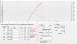
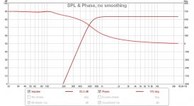
I tried generating LR8 650Hz target curves in rePhase, to use in REW.
I can not get the phase right down low. I have tried a lot of different settings in rePhase.
What am I doing wrong?
I am trying to go between rephase-REW-rephase, to learn.
I tried generating LR8 650Hz target curves in rePhase, to use in REW.
I can not get the phase right down low. I have tried a lot of different settings in rePhase.
What am I doing wrong?
Attachments
- Home
- Design & Build
- Software Tools
- rePhase, a loudspeaker phase linearization, EQ and FIR filtering tool