Is that a filter with constant phase lag of 36 degrees for all freq 100 to 400?
Then the Phase EQ can be used?
IME, FIR for low frequency should not be used unless the tap is extremely long (60000+). Too much audible negative effect.
OK what about this kind of FIR filter? I want a variable delay that is directly proportional to the frequency.
Hello,
As variable time delay can't exist, i suppose you have to choose the best :
either variable phase delay ( -36°) easy for your purpose,
or variable group delay : a constant slope phase curve
(seen with log frequency scale )
to have a group delay proportionaly decreasing with period.
cdt
Can rephase make these filters or do you use other tools?Hello,
As variable time delay can't exist, i suppose you have to choose the best :
either variable phase delay ( -36°) easy for your purpose,
or variable group delay : a constant slope phase curve
(seen with log frequency scale )
to have a group delay proportionaly decreasing with period.
cdt
I tried with the Phase EQ but not so easy to get a nice sloping group delay.
I could be wrong if its use full for requested situation but as inspiration look the phase shufler Pano did over http://www.diyaudio.com/forums/multi-way/277519-fixing-stereo-phantom-center.html. Phase turn is not very much but just enough to hinder some combing cancelation, pos kindly build this shufler into Rephase as preset under "Paragraphic Phase EQ".

Attachments
I'm trying to correct the phase issue of a rear firing woofer cancelling with the front woofer because of the difference in path length.
How do I create a variable delay filter that in rePhase to compensate for this phase delay of the rear woofer?
Thanks
What is the path length?
In terms of distance it will be a short time delay. In terms of frequency wavelength you would have to have an enormous box for that to be a true consideration.
Wire the woofers so that when you touch a battery to the set they both push out on a positive to positive tap on a 1.5 volt battery. That will give you a useful output from both drivers. To actually get a cardoid response over a useful bandwidth you will have to have done a purpose design enclosure. A guess is that you have a subwoofer enclosure with front and rear firing woofers?
If that is the case then you have the solution with the wiring the pair correctly.
What is the path length?
In terms of distance it will be a short time delay. In terms of frequency wavelength you would have to have an enormous box for that to be a true consideration.
.
If the woofers are 1 meter apart, the wavelength of cancellation between the woofers are 2 meter or 170 Hz. If the woofers are a part of opposing walls there will be an cancellation at 4 meter wavelength or 85 Hz. So that is quite a big, but not crazy big. For example a tube laying near the corner along the side wall.
I agree. That is part of the region where the subwoofer will have a cardioid response. At points where the path length between the two driver is at a half wavelength or less. But that is a little out of the range where most people use their subwoofers. I generally cross them over with a steep slope at or around 160 hertz. The greatest power in what we call bass in most music is then covered by the driver and enclosure most suited for it.
IME, FIR for low frequency should not be used unless the tap is extremely long (60000+). Too much audible negative effect.
Hello;
If you consider i am offtopic or at least half off topic please let me know;
So here it is
In response to a FIR (which to my understanding adjusts the arrow of gain to the desired response) would not be best to devise an "infinite impulse response" filter by the means of using analogue filtering (much like a RIAA corrector)? Ofcourse this can only be achieved by using RePhase and obtaining the correction curve.
My point (and question at the same time) is that the equivalent of the fir can be obtained with infinite resolution by the means of using an minimum phase analogue filter and easily anticipating and in the same time correcting its influence.(?)
Kind regards,
Calin.
A lot of the amplitude response can be realised with 2. Order analog filters. To also correct the phase and groupdelay is much harder, on the edge to impossible.
Analog filters ; yes can not by any means give phase linearization in a practical way but they come close and they can bring the sound where the ear can or no lomnger care of the shift.
My attempt is using a passive filter RC and a "no feedback rule" in the preamp stage to compensate filter's losses, allowing me to correct the amplitude gaps and phase shifts induced by speakers and room, and yelding the results of a digital FIR correction and response measured with basic tools like UMIK1 and REW+Rephase and confirmed by an audition.
Basically in any phase shift point(kindly revealed by rephase)... calculate and add an inverter of the same slope and opposite direction, compensating phase shifts induced by speakers filters and linearise the amplitude at the same time.
I have the rephase correction curve reproduced as simulation in ltspice and applied as a passive filter in a no-feedback preamp stage using K170's to compensate the losses from a 1V line in signal.
Maybe anybody can devise the math and crunch the numbers more efficiently and easily (since it took me ages to devise a curve based on the one given by Rephase).
As a great plugin for the RePhase tool(or external) would be nice to have one that takes a curve and generates a rough approximation of an analog filter that gives the correction made in Rephase (a nice project i have in mind but i have too few knowledge to start).
Anywho... i am getting far from the subject that is with no automated tools(although nice to have to save lots of TIME), and just the basic math of the filtering i achieved a rough correction of both amplitude and phase shift of my audio system based on a umik1+rew measurement and RePhase correction .... if anybody is interested and wants to improve or work on its own, i can layout my resulting ltspice sym and RePhase startig curve or even my resulting schematic and board layout (not sure if any practical use using the same values... but as a good/wrong example to go forward to a infinite response filter for correcting for his/her own audio chain and room shifts and attenuation
 )
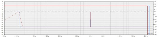
)Tried to import an textfile of -36 degrees and 0 dB into rePhase.
The FIR was generated, but the constant phase shift disappears in REW so I don't know if it works? (as i can't check the groupdelay.)
The import measurement in rePhase is just a visual support.
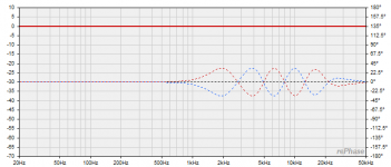
You might do effective -36° phase shift ( +/- 1°) this way:
An externally hosted image should be here but it was not working when we last tested it.
@escucalin: Using an IIR can do what an analog filter can do in the audiodomain. Nowadays high precision IIR has more accurate responce than an analog filter if it's not done with outmost care.
An all analog chain is nice, though.
I would be curious to see a digital IIR convolver that is not sample rate dependent and that does the job (so far i got ~success only Jriver's convolver with FIR with 65536 taps @ 96KHz sample rate and it was applied to any sample rate i feed it ... mostly 44* with amaizing correction... maybe jriver automatically resamples... i cant tell) So i got insanely frustrated being stuck in the jriver cage and went the analogue way with infinite taps
and godlike sound of jfets.
Last edited:
IIR is by definition not a convolver. FIR can implement normal IIR filters but they are still FIR. To me ADC-IIR-DAC = analog filters if done right.
Agree rephase is very nice tool to quickly test filters that later may be realised in FIR, IIR or analog. Dependent on your reqirements or believes.
Agree rephase is very nice tool to quickly test filters that later may be realised in FIR, IIR or analog. Dependent on your reqirements or believes.
Is there any research on how long the FIR filters can be before it does not make a difference to the human brain?
I think in seconds.
Does it help to correct/change sounds that was generated 1 second ago?. 0.1 second? 10 seconds?.
Another view of the question is how low 1/T frequency resolution can be detected in the audio bandwith.
Thinking of normal living room RT60 values here.
I think in seconds.
Does it help to correct/change sounds that was generated 1 second ago?. 0.1 second? 10 seconds?.
Another view of the question is how low 1/T frequency resolution can be detected in the audio bandwith.
Thinking of normal living room RT60 values here.

Hi again folks,
Been reading along , great info as usual .
Pos thank you for 1.2 it's fantastic!
I had a question maybe some y'all might be able to give some advice.
I want to make a dual passband filter in fir
What I've done is make a linear phase crossovers at 80 and 1.6k than use paragraphic gain eq and made stop band go to 90db setting
And made a cut at (around can't remember) 630 with a Q of 1 and a cut at 400 with a q of 1
I used cosine filter (it looked fairly smooth) all minimum phase filters in the eq
I only used about 20db cut seems to work pretty decent.
I was wondering if there is something I should try to make it better.
The reasoning behind this is the HF driver has 24" between the midrange and the midbass is right next to the HF driver.
So I want the midbass to meet the HF driver and joining the mid at a frequency where wavelength isn't a issue and where there's the least amount of comb.
It's in a car, have a horn on dash , a midbass on dash and a midrange in kick panel.
So if I left mid on the dash has such extreme combfilters with deep notches at 300-600-900 and huge peaks at 200-400-800-
So the kick panel works better for the midrange but doesn't blend with the horn because of the distance , so I have the midrange playing 250-800 and the midbass playing 80-250 and than again at 800-1.6k
It sounds pretty good, it works pretty well and I'm on to something good I do believe,
Just wondering if there's a way to actually make a dual passband filter with rolloffs that match a LR alignment or something?
Thanks in advance ,
Sorry such a weird request
Last edited:
- Home
- Design & Build
- Software Tools
- rePhase, a loudspeaker phase linearization, EQ and FIR filtering tool