What are the practical implications of this
linkwitzlab.com/frontiers_7.htm#D2
It seems that a dipole loudspeakers with varying baffle width (Like NaO Note) can experience problems when standard crossover is used.
I did brief experiment before which although measures well, never sounded right and was quite suspicious about the baffle size transition. Although never been able to explain it.
www.diyaudio.com/forums/multi-way/161681-my-s13-ob-uniform-polar-response-tweeters-last-2.html#post2097027
And what about no-baffle dipoles ??
The axial response of any unequalized dipole will with have a phase response will be zero at the dipole peak and approach 90 degrees at DC. Above the dipole peak the response will exhibit the usual peak/null behavior. The higher the dipole peak in frequency (smaller D), the more rapidly the phase approaches the DC value of 90. However, once the response is equalized to some band pass, the axial response of that band pass will be the same as that of a boxed driver with the same band pass because the axial response of a dipole, equalized or not, is minimum phase. The net result is that axial sum is no different than that of summing monopoles in that the different AC positions must be considered. Of course, the problem with using true dipoles above the dipole peak is that the nulls can not be eq'ed. But driver directionality is usually used to counter that effect.
You brought up my NaO Note. Just where are these problems SL alludes to in it's axial response?
The bottom line is that this is no different than a typical box speaker. You measure the axial amplitude and phase response of each source. That response will be minimum phase plus some contribution for AC offset. That there may be a phase difference due to the position of the dipole peak (or D) is no different that the observation that an LP filter with cut off of 1k Hz Hz has different phase at 100 Hz than an LP filter with cut off of 300 Hz. It's much ado about nothing; SL is just making things seem more complex than they are, as he typically does.
You brought up my NaO Note. Just where are these problems SL alludes to in it's axial response?
An externally hosted image should be here but it was not working when we last tested it.
The bottom line is that this is no different than a typical box speaker. You measure the axial amplitude and phase response of each source. That response will be minimum phase plus some contribution for AC offset. That there may be a phase difference due to the position of the dipole peak (or D) is no different that the observation that an LP filter with cut off of 1k Hz Hz has different phase at 100 Hz than an LP filter with cut off of 300 Hz. It's much ado about nothing; SL is just making things seem more complex than they are, as he typically does.
Linkwitz is talking about the delay of the combined front and back radiation (as seen from the front) of an open baffle dipole. He is essentially saying that since the rear radiation that gets around to the front is significantly delayed the combined output is delayed as the vector sum of the two. This is all true and is another way of describng why the unequalized dipole rolls off at lower frequencies. It is still minimum phase and equalization of the dipole response to flat will improve the phase.
The curves he shows are typical summation of a delayed woofer and less delayed midrange. this looks like a lot of delay to me. Except for the case of adding a short tweeter horn to a long mid horn I never see multiple rotations (the ripple) as he is showing. Recessing the mid could bring them well into phase. I guess SL's argument is that the dipole section will need more delay compensation (electrical or physical) but I'm not sure I would generalize to that extent.
David S.
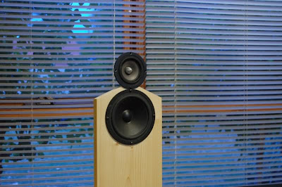
John, that looks almost anechoic flat. What type of measurement is this? Anechoic on axis, quasi-anechoic, spatially averaged, or is it the simulated response? Do you have a listening position response in your room?
The response shown is a combination of a 1/6 octave smoothed far field (1M quasi-anechoic) measurement combined with a dipole corrected near field measurement below 385Hz.
Linkwitz is talking about the delay of the combined front and back radiation (as seen from the front) of an open baffle dipole. He is essentially saying that since the rear radiation that gets around to the front is significantly delayed the combined output is delayed as the vector sum of the two. This is all true and is another way of describng why the unequalized dipole rolls off at lower frequencies. It is still minimum phase and equalization of the dipole response to flat will improve the phase.
The curves he shows are typical summation of a delayed woofer and less delayed midrange. this looks like a lot of delay to me. Except for the case of adding a short tweeter horn to a long mid horn I never see multiple rotations (the ripple) as he is showing. Recessing the mid could bring them well into phase. I guess SL's argument is that the dipole section will need more delay compensation (electrical or physical) but I'm not sure I would generalize to that extent.
David S.
As I said, he is making it seem more complex than it is. The summed front and rear dipole response measured at any position (on or off axis) is minimum phase. The result that a dipole on a circular baffle of diameter D has different phase than one on a baffle of diameter D/x is simply a consequence that the dipole peak is shifted, yielding different amplitude, hence, minimum phase.
If you have a dipole source on a 10" circular baffle and another on a 3" dia. baffle and you could eq both to the exact same band pass response then they will have the exact same phase regardless of the dipole delay. The problem is that due to the nulls above the dipole peak the response above the peak can not be made identical in practice.
For example, in theory you could take the 10 dipole and eq it to a perfect B1 LP at 500 Hz and take the 3" dipole and eq it to a perfect B1 HP at 500 Hz and they would sum perfectly. The dipole delay would be negated by the eq.
If you have a dipole source on a 10" circular baffle and another on a 3" dia. baffle and you could eq both to the exact same band pass response then they will have the exact same phase regardless of the dipole delay. The problem is that due to the nulls above the dipole peak the response above the peak can not be made identical in practice.
For example, in theory you could take the 10" dipole and eq it to a perfect B1 LP at 500 Hz and take the 3" dipole and eq it to a perfect B1 HP at 500 Hz and they would sum perfectly. The dipole delay would be negated by the eq.
Yes, both assuming the drivers have alligned acoustic centers. (probably not the same baffle planes) It still isn't clear to me why the SL example shows as much phase rotation as it does.
David S.
Yes, both assuming the drivers have alligned acoustic centers. (probably not the same baffle planes) It still isn't clear to me why the SL example shows as much phase rotation as it does.
David S.
The thing is Dave, ask yourself, "How is this different from ordinary diffraction?" The answer is there really isn't any difference except the strength of the inverted wave. It makes no difference is the wave come from the rear and wraps around the baffle or if it's a surface wave that travels across the baffle and is then diffracted at the edge; the delay is the same. The difference is only in the strength of that diffracted wave. So the same type of argument can be made for any speaker, dipole, box, or otherwise. It's a simply matter of multiple minimum phase sources being summed to provide flat response on axis. You do what is necessary, add delay, slope the baffle, offset the drivers, what ever. The idea that this is some how a dipole problem is a misrepresentation.
I'll put up some figures later if I feel like it.
")
As for SL's phase differences, I think he is off by a factor of 2. I get about 16 degrees between mid and woofer for a 10 and 40 cm equivalent delay. Interestingly, if I do a crude box simulation for baffle step with similar baffles I get about the same "baffle diffraction induced" phase difference at 100 Hz. But again, this is corrected by baffle step compensation. The important thing to note that this is not the same as AC offset. This is phase difference due to differences in the amplitude response and the consequence of minimum phase. So I do not think it is correct to look at the phase difference between unequalized dipoles on different size baffles, at some particular crossover frequency, and conclude that that phase difference carries over to a necessary delay compensation for the crossover frequency.
So in summary the problem does not exist if the drivers are equalised appropriately on-axis ?
What software do you use to calculate simulate this?
Basically that is it, as long as you are concerned only with the forward axial response. Things get very complicated if you are trying to design a front-rear symmetric dipole.
I put togeter a short write up this morning; Dipole-mp
An interesting tutorial but I'm not comfortable with the "no delay" conclusion.
As I understand, you are starting with a wide band driver of no depth and a second similar unit with 10cm recess and you end up with a continuous downward roll of phase (that cycles with every null). I would have thought that this downward phase droop was evidence of the delay of the simulated dipole.
Comparing the unit's phase to the Hilbert transform of the same response isn't proof of no delay if the delay is inherent in the response itself.
David
The thing is Dave, ask yourself, "How is this different from ordinary diffraction?" The answer is there really isn't any difference except the strength of the inverted wave. It makes no difference is the wave come from the rear and wraps around the baffle or if it's a surface wave that travels across the baffle and is then diffracted at the edge; the delay is the same. The difference is only in the strength of that diffracted wave. So the same type of argument can be made for any speaker, dipole, box, or otherwise. It's a simply matter of multiple minimum phase sources being summed to provide flat response on axis. You do what is necessary, add delay, slope the baffle, offset the drivers, what ever. The idea that this is some how a dipole problem is a misrepresentation.
Yes, this is interesting and something that I didn't realize before playing with "the edge". The diffraction simulator allow modeling of a cabinet edge or converting it to an open back baffle of the same shape. The open back case tends to show the exact same ripple but with about twice the magnitude.
As for SL's phase differences, I think he is off by a factor of 2. I get about 16 degrees between mid and woofer for a 10 and 40 cm equivalent delay. Interestingly, if I do a crude box simulation for baffle step with similar baffles I get about the same "baffle diffraction induced" phase difference at 100 Hz. But again, this is corrected by baffle step compensation. The important thing to note that this is not the same as AC offset. This is phase difference due to differences in the amplitude response and the consequence of minimum phase. So I do not think it is correct to look at the phase difference between unequalized dipoles on different size baffles, at some particular crossover frequency, and conclude that that phase difference carries over to a necessary delay compensation for the crossover frequency.
I agree he is off by a factor of 2. I can confirm his formula is 360 * D *f / 34,000 cm/sec for 10.588 (times D over Lambda) but this is for the delay of the back unit. The vector sum is still half the delay of the two components rather than the delay of the rear elelment.
As to his simulation, it isn't really a simulation of dipoles sections summing as much as simply a first order high pass and first order low pass. Judging by the in and out of phase cycling at about a 5kH rate then the time difference between sections is about .2ms suggesting 2.7 inches or 6.8cm acoustic center offset.
David S.
An interesting tutorial but I'm not comfortable with the "no delay" conclusion.
As I understand, you are starting with a wide band driver of no depth and a second similar unit with 10cm recess and you end up with a continuous downward roll of phase (that cycles with every null). I would have thought that this downward phase droop was evidence of the delay of the simulated dipole.
Comparing the unit's phase to the Hilbert transform of the same response isn't proof of no delay if the delay is inherent in the response itself.
David
What this shows is that the phase of the summed front and back is minimum phase relative to the location of the front source, when veiwed front the front. That it is minimum phase means that minimum phase equalization to any target will yields the minimum phase target. There is no particular need to compensate for delay introduced by the summation. All that is required is to account for AC offset, if they are present. No different than a box speaker.
Contiuous downwards phase roll is evidence of delay.
Minimum phase does not mean free from delay but free from excess delay.
Clearly if we add two equal strength vectors, one delayed, then the combined vector is from the mid point between the two. Before the first dipole null this is obvious by inspection. I don't think giving the combination a minimum phase correction and then analyzing the delay is actually a fair way to look at it.
David S.
I'm not saying there is no delay in the response, just that it is inherent in the minimum phase response. If rather than referencing the phase to the front source AC I reference it to the physical center of the dipole (2 sources separated by a distance, D, the phase looks like this:

This is the same case as show on my site for two sources separated by 10 cm except in this case the phase is relative to a position 1/2 way between the sources rather then to the location of the front source. You will see this same behavior regardless of the separation, D. That is, the dipole phase, relative to the position 1/2 way between the sources, will be constant and 90 degrees up until the first dipole null. Then it flips between +/- 90 as shown. This is not either minimum phase or constant delay.
This is the same case as show on my site for two sources separated by 10 cm except in this case the phase is relative to a position 1/2 way between the sources rather then to the location of the front source. You will see this same behavior regardless of the separation, D. That is, the dipole phase, relative to the position 1/2 way between the sources, will be constant and 90 degrees up until the first dipole null. Then it flips between +/- 90 as shown. This is not either minimum phase or constant delay.
Contiuous downwards phase roll is evidence of delay.
I don't think giving the combination a minimum phase correction and then analyzing the delay is actually a fair way to look at it.
David S.
Certainly it is. We are summing the equalized dipole response so the phase of that response is what is relevant. What else would you propose?
I think we are getting a bit circular in our arguments but here is where we started from: Linkwitz talks about the effective delay of a dipole and how it is impacted by baffle width. If response is the combination of the front element vector and the back element vector (assuming the back as strong as the front) then the baffle width determines the delay time and the total effective delay is half the difference.
I believe that is a true statement and I think your curves are showing the same thing. Your most recent one with phase shown relative to the mid point between the two drivers (real and delayed rear element) shows a more plausibly flat phase. I conceed that it isn't flat extending from the origin but rather is +-90, but this still looks like no delay rather than the previous one with constantly drooping phase, a guarantee of time delay.
As a thought experiment we can think of a di'appolito pair. Lets fix the lower one at 1 meter in space and let the second receed in an arc at a constant spacing around the first. Clearly the effective delay of the pair increases as the upper unit receeds. It will always have an effective depth equal to the mid point between the two drivers, or half the set back of the top unit.
Now push the top unit all the way back to where it is directly behind the first (and flip the polarity) and you have your simulated dipole. At what point did the mid point between the two woofers cease to be the acoustic center of the pair?
David S.
First realize that the AC is not a fixed point. It is simple some point we defined based on where the phase response corresponds to the minimum phase. It's fairly easy to define its position for an on axis measurement. We assume it is on the driver's (or source's) axis and all we do is figure the position along the axis. But measure the same source at 45 degrees and all you can say is that the AC for that position is on some arc drawn with its center at the observation point. If we choose to say it must still be on the driver's axis there is no reason to suspect it is located at the same position as that for the axial AC. The AC is not a fixed point, as I noted before in this discussion where it is observed that the AC for a dipole changes depending on whether you look at it from the front or rear.
My original point was that SL has gone through an argument about delays and compensation that boils down to the fact that he has chosen to position the sources with their ACs offset. If you choose to align two dipole sources so that they are physically aligned based on the 1/2 way point between the front and rear sources of each dipole then you are intensionally misaligning the AC. For example, for the 10 and 3 cm separation set the sources of the 10 cm dipole at +/- 5 cm and those of the 3 cm separation at +/- 1.5 cm and you can talk about delays and show the effect on summed response as SL does. And that is corrected by correcting for the 3.5 cm relative offset of the ACs. And, if the dipole sources are truly symmetrical this correction will work for both the front and rear response. I discussed this years ago on my web stie but I took it down to make a couple of corrections to the terminoloigy I used. But the idea was the same.
The other thing to realize is that if you choose to correct this by physically moving one source relative to the other, you will have to move the midrange forward, not back, because the AC of the dipole woofer is further forward than that of the mid range. The image below shows the summed response in red with the two dipoles aligned to their physical center and the green trace is the summed response when the AC offset is corrected by delaying the woofer by a time equal to 3.5 cm/sound speed.
Anyway, I go back to waht I said initially. It is much ado about nothing. It's just addressing acoustic center offsets like any other speaker.
My original point was that SL has gone through an argument about delays and compensation that boils down to the fact that he has chosen to position the sources with their ACs offset. If you choose to align two dipole sources so that they are physically aligned based on the 1/2 way point between the front and rear sources of each dipole then you are intensionally misaligning the AC. For example, for the 10 and 3 cm separation set the sources of the 10 cm dipole at +/- 5 cm and those of the 3 cm separation at +/- 1.5 cm and you can talk about delays and show the effect on summed response as SL does. And that is corrected by correcting for the 3.5 cm relative offset of the ACs. And, if the dipole sources are truly symmetrical this correction will work for both the front and rear response. I discussed this years ago on my web stie but I took it down to make a couple of corrections to the terminoloigy I used. But the idea was the same.
The other thing to realize is that if you choose to correct this by physically moving one source relative to the other, you will have to move the midrange forward, not back, because the AC of the dipole woofer is further forward than that of the mid range. The image below shows the summed response in red with the two dipoles aligned to their physical center and the green trace is the summed response when the AC offset is corrected by delaying the woofer by a time equal to 3.5 cm/sound speed.
An externally hosted image should be here but it was not working when we last tested it.
Anyway, I go back to waht I said initially. It is much ado about nothing. It's just addressing acoustic center offsets like any other speaker.
I think what he is saying that is interesting is that the effective acoustic center location varies with baffle diameter.
That is different than with conventional drivers where you might choose a network that works with your physical delay or pick a network and then vary delay (physical or electrical) to make it work. He is pointing out that the physical offsets between drivers (say voice coil locations) won't give you the full answer. You have to then look at baffle diameter since varying it will change the acoustic center location, even with no other physical changes.
Correct me if I'm wrong, but I don't believe you have disproved that.
Acoustic center of the woofer is forward of that of the midrange?
David S.
Hi,
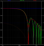
I did a simulation of Dave's scenario, using two point sources, 3ms delay and polarity flip, then EQd to flat with a pole at 1Hz.
This was compared to a mag and phase curve fitting done with minphase elements, 2nd order lowpass and notch. Actually group delay was used for fitting.
See plot #1 :
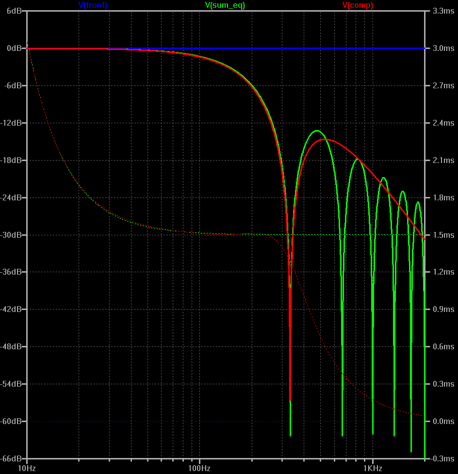
The close fitting of the curves up to the dipole notch is noticable. The dipole group delay settles in at 1.5ms, half the delay time.
Same thing, with phase this time :

Note that the phase is plotted unwrapped. The "jumps" (discontinuities) are only 180°, not 360°
Now, the time reference was moved "midway in between" the sources :
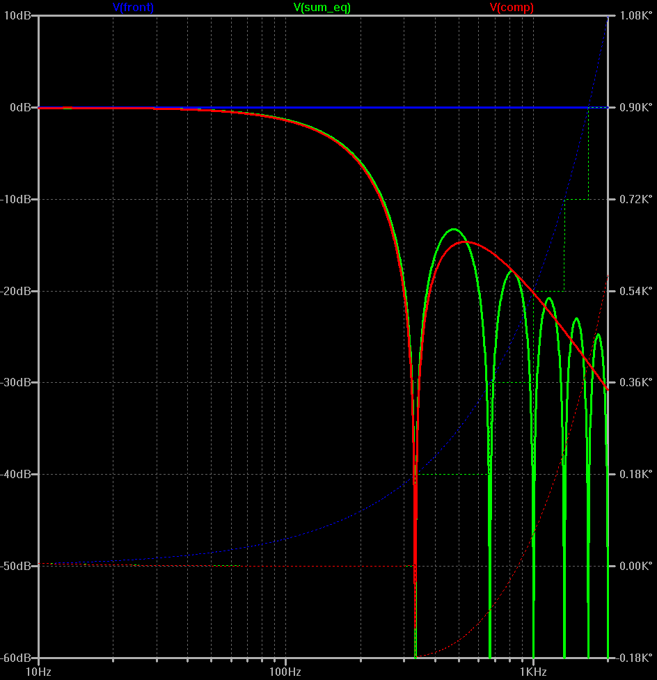
This time we get an unwrapped phase "staircase" for the dipole, while the front source and the minphase model have unwrapped positiv phase rolloff, indicating negative delay. Wrapped phase would result in a "square" phase like seen on John's earlier plot.
(Group delay looks the same as above, only offset by 1.5ms.)
I did a simulation of Dave's scenario, using two point sources, 3ms delay and polarity flip, then EQd to flat with a pole at 1Hz.
This was compared to a mag and phase curve fitting done with minphase elements, 2nd order lowpass and notch. Actually group delay was used for fitting.
See plot #1 :
The close fitting of the curves up to the dipole notch is noticable. The dipole group delay settles in at 1.5ms, half the delay time.
Same thing, with phase this time :
Note that the phase is plotted unwrapped. The "jumps" (discontinuities) are only 180°, not 360°
Now, the time reference was moved "midway in between" the sources :
This time we get an unwrapped phase "staircase" for the dipole, while the front source and the minphase model have unwrapped positiv phase rolloff, indicating negative delay. Wrapped phase would result in a "square" phase like seen on John's earlier plot.
(Group delay looks the same as above, only offset by 1.5ms.)
Attachments

Last edited:
- Status
- This old topic is closed. If you want to reopen this topic, contact a moderator using the "Report Post" button.
- Home
- Loudspeakers
- Multi-Way
- Phase shift due to dipole D and its effect upon crossovers