A Paraline sub seems like an interesting alternative to the multiple sub approach, because it's not too hard to make the mouth six, eight, or even twelve feet long!
There's one catch though - and that's the humongously long wavelengths. For instance, this experiment started when I was trying to make a 40hz Paraline. Due to the radial expansion of the Paraline, a 40hz Paraline subwoofer ends up being over 7' x 3.5'!
If a 40 Hz Paraline sub is ONLY 7' X 3.5' then I should be able to do a 20 Hz sub with 16' X 8', correct? If so, cool.
If a 40 Hz Paraline sub is ONLY 7' X 3.5' then I should be able to do a 20 Hz sub with 16' X 8', correct? If so, cool.
You had better post a video of that.
lmfao.
A Paraline sub seems like an interesting alternative to the multiple sub approach, because it's not too hard to make the mouth six, eight, or even twelve feet long!
There's one catch though - and that's the humongously long wavelengths. For instance, this experiment started when I was trying to make a 40hz Paraline. Due to the radial expansion of the Paraline, a 40hz Paraline subwoofer ends up being over 7' x 3.5'!
So the reason my Paraline has a square mouth instead of a long skinny one is that I was stacking a Paraline on a Paraline. By doing that, you cut the footprint in half.
I was doing the math in my head, and I was off by a factor of two. An 'eye-shaped' Paraline tuned to 40hz measures approximately 14' x 7'. This is because 40hz is 28.125' long, and our horn is tuned to one-quarter wavelength of that (7.03'). So the 'Paraline Pancake' has a radius of 7.03', and once it's folded it ends up being 7.03' wide by 14.16' tall.
I was doing the math in my head, and I was off by a factor of two. An 'eye-shaped' Paraline tuned to 40hz measures approximately 14' x 7'. This is because 40hz is 28.125' long, and our horn is tuned to one-quarter wavelength of that (7.03'). So the 'Paraline Pancake' has a radius of 7.03', and once it's folded it ends up being 7.03' wide by 14.16' tall.
Which would make the 20 cycle version ...*looks out the window into the back yard* yeah, the addition can go right over here...
As a 200hz -> 15000hz driver, this looks pretty cool though. I'm watching this for more details, I spent quite a bit of time this morning googling designs and I really want to try one. I wonder if any of my spare drivers are suitable for a test.
I was doing the math in my head, and I was off by a factor of two. An 'eye-shaped' Paraline tuned to 40hz measures approximately 14' x 7'. This is because 40hz is 28.125' long, and our horn is tuned to one-quarter wavelength of that (7.03'). So the 'Paraline Pancake' has a radius of 7.03', and once it's folded it ends up being 7.03' wide by 14.16' tall.
[/font]
Right. I should have known better. Confession time. I have an old school exponential bass horn that projects into the corner of my listening room. It is 22 feet long and is tuned to about 28 Hz. I built it a long time ago, before hornresp and tapped horns, when I knew even less about horns than I do now. The laws of physics haven't changed in the intervening time.
Sigh.
Which would make the 20 cycle version ...*looks out the window into the back yard* yeah, the addition can go right over here...
As a 200hz -> 15000hz driver, this looks pretty cool though. I'm watching this for more details, I spent quite a bit of time this morning googling designs and I really want to try one. I wonder if any of my spare drivers are suitable for a test.
But the cool thing is that it's still skinny!
An externally hosted image should be here but it was not working when we last tested it.
For instance, let's say you want to make a Paraline out of a sheet of 4'x8' lumber. To make it 'disappear', you turn it into a room divider. A room divider is ideal, because it gives us an opportunity to put the loudspeaker in the center of the room, away from boundaries, where loudspeakers sound best.
Now you might think that if you went with a 4'x8' Paraline that it would have to be a couple of feet thick, but it doesn't. In fact, it's better if it's skinny because skinny plays higher in frequency.
And a 4'x8' foot Paraline goes pretty deep - all the way down to 70hz. That's plenty low to mate up with some subs.
If you want to go 'Full Monty' just subdivide the whole room. A Paraline thats 8' tall by 16' wide will play down to 35hz. Now 35hz doesn't sound too low, but this IS a horn after all, so we're going to get all the efficiency and dynamics that come with that... In a package that's 1.25" deep
")
....but this IS a horn after all, so we're going to get all the efficiency and dynamics that come with that... In a package that's 1.25" deep
This is exactly why I'm itching to try one of these. I've had my hands dirty with box speakers for a number of years...I'm looking for some new stuff to eff with. What's in your video looks just elegant enough to be the ticket. I even went and looked at BMS compression drivers this morning to see how much this would cost me if I went full monte on it.
Interesting design- certainly has lots of applications, though my concern would be with the huge internal reflection mechanism, a very narrow radius 180 degree bend, and then another rapid bend/termination at the end.
But still very cool!
Reflections, high order modes, diffraction, and all that terrible stuff can't occur when the size of the wave is much much bigger than the duct that it's moving through. For example, you can't make a tidal wave in a swimming pool - the pool is simply too small to contain it.
That's why the height of the horn is just 1/4". That height means that any wavelength below 18,000hz simply can't form in the device. (The wave forms at the mouth.)
The formula is (wavelength / duct height / 3 ) or (34,000cm per second / 0.635cm / 3)
They can't form as standing waves or reflections between the parallel surfaces in any meaningful fasion, no. My concern is with the larger dimension- 4-5" long or more, in which a wave can encounter the obstacle that is the 18 degree turn.
We're talking 3d- any one dimension can create a problem in this respect. Normal considerations are for straight or VERY mildly curved ducts.
We're talking 3d- any one dimension can create a problem in this respect. Normal considerations are for straight or VERY mildly curved ducts.
Talaerts - the clearest drawings are in the patent application and are very helpful in explaining what's going on in principle.
Like Badman, I'm not clear why there aren't reflections at the bend - that distance must be long enough to be a 1/4 wavelength of some frequency in the passband. Maybe there is but it just isn't audible?
Like Badman, I'm not clear why there aren't reflections at the bend - that distance must be long enough to be a 1/4 wavelength of some frequency in the passband. Maybe there is but it just isn't audible?
Talaerts - the clearest drawings are in the patent application and are very helpful in explaining what's going on in principle.
Like Badman, I'm not clear why there aren't reflections at the bend - that distance must be long enough to be a 1/4 wavelength of some frequency in the passband. Maybe there is but it just isn't audible?
I can see the resonances being spread-spectrum due to the dissimilar pathlengths, but I'd think it'd still impose a rather significant sonic signature- likewise the termination would want a well-made phaseplug and horn assembly to soften the transition.
I have a couple 3d shapes in mind that would mitigate this challenge, but they're 3d and as such would be exceedingly difficult to explain or build.
Gentlemen,
Is there somewhere an article with drawings about the principle of this innovative approach. I looked at Patrick's youtube videos and I still don't understand how it works.
Here's the picture from Danley's patent.
Here's a quick overview of how it works:
An externally hosted image should be here but it was not working when we last tested it.
In a conventional conical horn, the horn has width and depth. For instance, you might have a ninety degree conical horn with a depth of 7.5" and a width of 15". There are lots of ways to fold a conventional horn. The pic above shows one of them.
In a conventional horn, the apparent location of the sound varies based on frequency. Basically, high frequencies seem to emanate close to the throat, while low frequencies seem to emanate from the mouth. You can get an appreciation for this by putting your head in front of a folded horn. You'll hear high frequencies seem to come from deep inside the horn. The reason that this happens is that low frequencies dwarf the dimensions of the horn. So you get this wonky situation where the apparent location of the sound is variable. The simplest way to fix this situation is to use a horn with a larger coverage angle, a shallow horn, or both. This has been documented by the AES, I can dig up articles if you want. The Paraline folding attacks the problem from the exact opposite direction. Instead of using a wide shallow horn to fix this problem, the Paraline folds it into a shape that's so small, the diffraction and HOMs can't even form inside of the device. In my videos on youtube, you can hear this for yourself. The Paraline plays audibly higher in frequency than a conical horn, and I would argue that this is because there's no cancellation and comb filtering inside of the device.
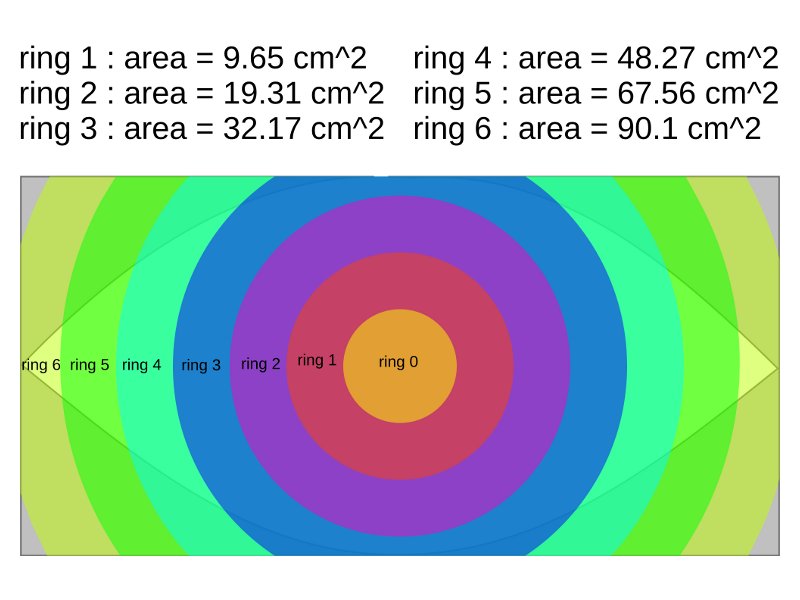
A Paraline is a horn that radiates in 360 degrees. Picture a series of concentric rings, like the illustration that I made above. You can get a good idea of it's performance by modeling it in hornresp. The main difference is that the depth of the horn is equal to the radius of the ring. For instance, a ring with a diameter of 12" will behave like a horn with a depth of 6".
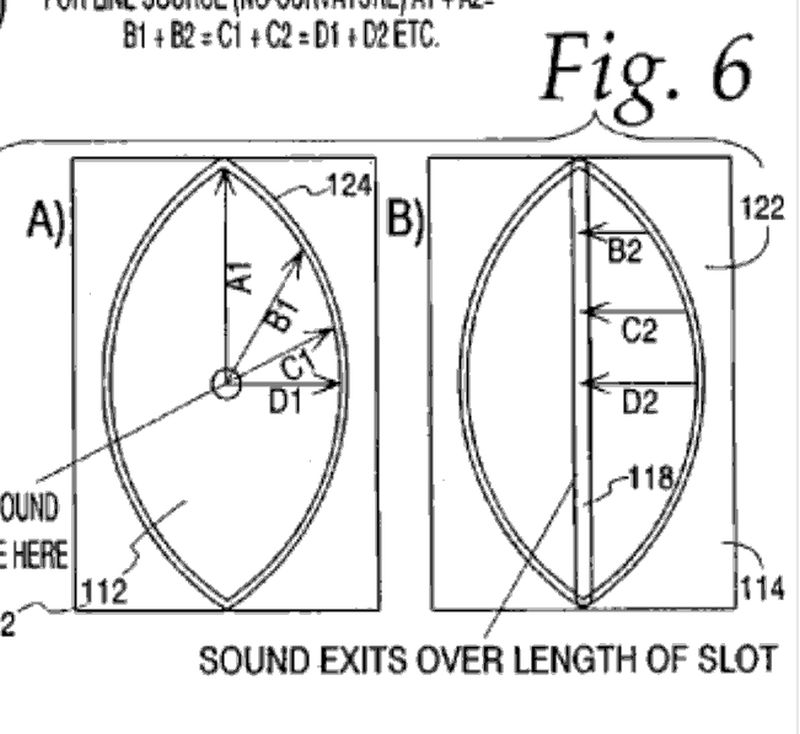
To keep size to a minimum, the horn in the Paraline is folded. For instance, sound emanates from the hole in the center, where the driver is located, proceeds along line D1, is folded over, then continues to proceed over line D2.
There is nothing magical about this device; it's a conical horn that's been folded in a very clever way. But since it's a conical horn, it's a very attractive option for a lot of our projects. For instance, the tapped horns that we've been building like crazy are also conical horns. And, yes, you can make a Paraline into a tapped horn. (Instead of mounting the driver from the back, mount it from the front, with the magnet sticking out of the mouth. Voila! Tapped Paraline horn.
[/font]
Last edited:
Top Shelf - the patent application says mutliple folds are possible.
Patrick - you've obviously read most about this. Is there anywhere where Tom Danley explains about the exit mouth shape? The patent application for the 'eye' paraline is obviously all about creating a line array effect. But the idea of using a radially concentric expansion to reduce horn depth is a separate issue. I'm interested in both, but I can't quite see how to reduce the height of the eye paraline for lower frequencies. I think it has to be 1/2 wavelegth of the lowest frequency you want. Maybe I missed this in the patent description.
Patrick - you've obviously read most about this. Is there anywhere where Tom Danley explains about the exit mouth shape? The patent application for the 'eye' paraline is obviously all about creating a line array effect. But the idea of using a radially concentric expansion to reduce horn depth is a separate issue. I'm interested in both, but I can't quite see how to reduce the height of the eye paraline for lower frequencies. I think it has to be 1/2 wavelegth of the lowest frequency you want. Maybe I missed this in the patent description.
One thought from looking at the patent pictures and Patrick's proof of concept model:
The layer with the eye shaped slot will likely need to be very stiff, or braced near the middle, to avoid vibration caused by the high pressures from the driver(s). The vibration would cause it to act as a diaphragm and radiate sound directly out of the slot. In the commerical 2-driver Paralines, they appear to have made the plates from aluminium.
Patrick, I see the ends of some pieces of scrap ply visible in the mouth of your proof of concept, are they to brace the "eye shaped slot" layer? If I were going to build such a model out of ply, I'd mount the drivers with long bolts passing through all layers, with spacers over the bolts where they pass through the voids. This would apply bracing at the point(s) of maximum pressure.
As described in the patents, the Paraline appears to be a way to generate a plane wavefront for applications requiring a "line source", rather than as an impedance matching device. It's what I would call a waveguide rather than a horn. Then I look at Patrick's Proof Of Concept, and I suspect it works differently. I assume his model has a radially expanding first part fed by the drivers, a circular (rather than eye shaped) slot, and a "circular" (sort of square) exit. I keep visualising it as a diverging conical horn capped with a converging conical horn, but this ignores the "two dimensional" nature.
Looking at the patent, Fig. 14, imagine a second "item 30" connected in place of "item 32".That's what Patrick's model looks like to me. I must be missing something basic. (I know it's not my marbles, every morning I look in my toybox and there they are.)
Help...
Edit:
I wonder... if you built a device like Patrick's, and used multiple HF drivers clustered closely together in the centre, would the output at the exit combine into a virtual point source? Would this be the basis for a "layered combiner"?
Last edited:
Thanks all for the input, thanks to more pictures from the patent application I now finally see how it is folded between sheets.
What I don't really see is how the flat sheets will provide for a correct horn profile. In another forum I found a crosscut picture that shows the principle but without flat sheets, they would need to machined to properly follow a folded horn path:
In the patent application the layers look like an eye, I don't quite see why they shouldn't be circular? It must have something to do with the output hole being a slit.
In Patrick's prototype, you end up with a square output hole. Why wouldn't you end up with a circle instead?
What I don't really see is how the flat sheets will provide for a correct horn profile. In another forum I found a crosscut picture that shows the principle but without flat sheets, they would need to machined to properly follow a folded horn path:
An externally hosted image should be here but it was not working when we last tested it.
In the patent application the layers look like an eye, I don't quite see why they shouldn't be circular? It must have something to do with the output hole being a slit.
In Patrick's prototype, you end up with a square output hole. Why wouldn't you end up with a circle instead?
In the patent application the layers look like an eye, I don't quite see why they shouldn't be circular? It must have something to do with the output hole being a slit.
Yes. The distances A1+A2, B1+B2, C1+C2, D1+D2 are all equal (A2 is not shown because it is zero). So sounds leaving the driver at the same time exit the slit at the same time.
- Home
- Loudspeakers
- Multi-Way
- Square Pegs