
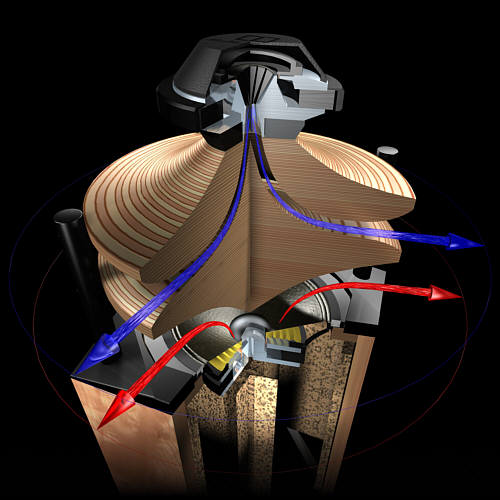
On this forum, Tom Danley has given us some information on some interesting new ways to fold a horn. These new horns include the VTC Paraline, which combines two compression drivers on one horn, and the Jericho J4, which uses what he calls a 'layered combiner' to load 64 compression drivers on one horn.
Unity Paraline - YouTube
I decided to build one this week.
Once you figure out how they work, they're a lot of fun to build. They're waaaaaaaaaay easier to assemble than a Synergy horn, that's for sure. I built this one in under two hours.
The device that I built is neither a Paraline nor a layered a combiner. For the most part, it's a simplification of the Paraline. (I could build a *real* Paraline, but I didn't want to for this project, I wanted to do a 'proof of concept' first.)
As usual, my projects are completely kludgey and rushed and crude, but you get the general idea.
In the video, I think you'll notice a few things:
#1 - Although my compression driver appears to be firing through a block of wood, I have extension out to at least 18khz
#2 - Have you ever seen a horn that was less than four centimeters deep?
#3 - Have you ever seen a Unity horn that was smaller than a 8" woofer?
Hope you enjoy the vid.
Cool video! VERY VERY interesting.
Will you be showing how you built it? I wanna try one.
Definitely.
Mine is way easier to build than a Paraline, but it's the same idea.
Everything you need to know to build this is in the Paraline patent. AFAIK only Danley has built one with the midranges on the Paraline, but it seems to work fine that way.
I'll upload some pics later this weekend, which show the internals of the thing.
Here's another video, showing how I am folding my Paraline-type device:
Paraline Folding - YouTube
The radiation of the Paraline is basically an ideal match for a ring radiator. The high frequency output of the Paraline seems to be far superior to a conventional conical horn. (For instance, with the same driver on a conical horn, my horn seems to run out of steam at 2khz. On a Paraline, the same midrange driver seems to go to about 5khz, well over an extra octave.)
Anyways, check out the video, I think it explains the folding in a understandable way.
I'll post some pics of the device assembly in the next couple days.
Paraline Folding - YouTube
An externally hosted image should be here but it was not working when we last tested it.
The radiation of the Paraline is basically an ideal match for a ring radiator. The high frequency output of the Paraline seems to be far superior to a conventional conical horn. (For instance, with the same driver on a conical horn, my horn seems to run out of steam at 2khz. On a Paraline, the same midrange driver seems to go to about 5khz, well over an extra octave.)
Anyways, check out the video, I think it explains the folding in a understandable way.
I'll post some pics of the device assembly in the next couple days.
Here's some more food for thought.
In my Paraline-type-thing, I have a square throat. One drawback to a square throat is that the output from one side could create comb filtering with the output from the other side. If you look at the Danley Paraline in the VTC Array, Danley has placed a phase plug in the mouth, which should reduce this problem.
But here's an idea of another way you can solve the problem.
You lay my Paraline-type-thing on it's side and now you're radiating in 360 degrees. Somewhat similar to the Duvel speaker pictured above, but in a foot print that's less than 1.5" deep, and much much much easier to build.
(Again, I built my Paraline-type-device in under two hours. It's super super super simple to build.)
I am listening to it this way right now, and it works very nicely as an omnipole. Seems to deliver the 'room sound' better than a typical speaker does.
As always, if this post makes no sense, please let me know. This Paraline thing is a bit mind-bending, and it took me a few weeks to grok all of the math. In my pic above, the idea is that the sound radiates in a ring inside the Paraline, and then at the Paraline mouth we create another ring radiator.
This harkens back to the traditional Unity horn concept of a conical horn stacked on a conical horn stacked on a conical horn. Except here we have a ring-shaped horn that feed *another* ring shaped horn. You could continue this across the entire frequency bandwidth. For instance, you could have tweeter, midrange, and low frequency all radiating in a ring.
In my Paraline-type-thing, I have a square throat. One drawback to a square throat is that the output from one side could create comb filtering with the output from the other side. If you look at the Danley Paraline in the VTC Array, Danley has placed a phase plug in the mouth, which should reduce this problem.
An externally hosted image should be here but it was not working when we last tested it.
But here's an idea of another way you can solve the problem.
You lay my Paraline-type-thing on it's side and now you're radiating in 360 degrees. Somewhat similar to the Duvel speaker pictured above, but in a foot print that's less than 1.5" deep, and much much much easier to build.
(Again, I built my Paraline-type-device in under two hours. It's super super super simple to build.)
I am listening to it this way right now, and it works very nicely as an omnipole. Seems to deliver the 'room sound' better than a typical speaker does.
As always, if this post makes no sense, please let me know. This Paraline thing is a bit mind-bending, and it took me a few weeks to grok all of the math. In my pic above, the idea is that the sound radiates in a ring inside the Paraline, and then at the Paraline mouth we create another ring radiator.
This harkens back to the traditional Unity horn concept of a conical horn stacked on a conical horn stacked on a conical horn. Except here we have a ring-shaped horn that feed *another* ring shaped horn. You could continue this across the entire frequency bandwidth. For instance, you could have tweeter, midrange, and low frequency all radiating in a ring.
Last edited:
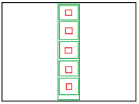
My understanding of the paraline is that the sum of the diferent pathlenght is always konstant if you dont want it to have a different shape of the waveform as i leaves the exit.
A neat trick you can use is to use a small lenght of string and fold it in half. One end you attach i the middle of the divice, the entrance for the speaker. And the other end of the string you move around on the edge of the shape of the exit "port".
And with the string folded and pulled straight out from the middle you will get the shape of the first cutout. The shape of the exit dont matter as long as the patch lenght is the same.
And a string cant change its lenght..
Great videos. Folding paper is a simple and elegant way to convey the idea.
As much as I value the contributions of experts like Earl Geddes, Tom Danley, Speaker Dave, John K... and others, it is your posts that really get my brain cooking. I see the Paraline as a device to change the radiation pattern of a driver to fit new environments.
How about this for radical? My listening room badly needs a new floor.The "temporary" floor has been in place for 25 years. How about a low frequency Paraline built into the floor with a 16 foot long exit slot running the length of the room? This should provide a different excitation of room modes than a single point source. Better maybe. Worse perhaps.
Not radical enough? How about a tapped low frequency Paraline. The same as above but using the radiation from the back of the driver to aid the radiation from the slot.
Still not radical enough? I know a low frequency Paraline won't act exactly like a double bass array but what about a "launcher" Paraline on the floor and a "catcher" Paraline on the ceiling.
Other than the obvious issues, the real problem is modelling the performance of the system. Anyone know of any tool that would help with this type of analysis?
How about a low frequency Paraline built into the floor with a 16 foot long exit slot running the length of the room?
I have the weirdest bon....nevermind.
Yeah, I could see this done with a couple of rows of 18s in a floor that was a couple of feet thick. My lord.
Member
Joined 2009
Paid Member

looking forward to device assembly pics. A ring radiator, btw, refers to the diaphragm assembly, it's not radiating in a ring- it's effectively omni, and intended to have less off-axis cancellation by the combined phasing plug and more narrow acoustic source cross section.
Yeah, I could see this done with a couple of rows of 18s in a floor that was a couple of feet thick. My lord.
Actually, I was thinking about using one shallow mount 12 inch driver. Assuming an Sd of about 95 in^2 and a Paraline "throat" area of 50% of that, then the depth between layers is about 1.25 inches. The total floor thickness, using 1 inch thick wood, then is 1 + 1.25 + 1 + 1.25 + 1 = 5.5 inches. The slot width needs to be about 3.2 inches.
Actually, I was thinking about using one shallow mount 12 inch driver. Assuming an Sd of about 95 in^2 and a Paraline "throat" area of 50% of that, then the depth between layers is about 1.25 inches. The total floor thickness, using 1 inch thick wood, then is 1 + 1.25 + 1 + 1.25 + 1 = 5.5 inches. The slot width needs to be about 3.2 inches.
Ah, right. I was thinking of it as multiple units. Considering the size of one of these with a driver that was tuned appropriately low, what popped into my head was similar to a flown array, but built into a floor with a line of openings.
In my head, things are always disproportionately large, it's a man curse.
E.G.: (pic)
Attachments
Great videos. Folding paper is a simple and elegant way to convey the idea.
As much as I value the contributions of experts like Earl Geddes, Tom Danley, Speaker Dave, John K... and others, it is your posts that really get my brain cooking.
Wow, that's a bit humbling! But thank you
")
I see the Paraline as a device to change the radiation pattern of a driver to fit new environments.
How about this for radical? My listening room badly needs a new floor.The "temporary" floor has been in place for 25 years. How about a low frequency Paraline built into the floor with a 16 foot long exit slot running the length of the room? This should provide a different excitation of room modes than a single point source. Better maybe. Worse perhaps.
Actually, that was the idea that got me started on these crazy Paraline experiments.
Here's my situation:
I have my Gedlee Summas in my bedroom. I have three subwoofers, including one that weighs something like 350lbs. (It's documented in the 'night of the living bassheads' thread here on diyaudio.)
Multiple subs *definitely* work - but I'm really sick of having all these ugly subs.
So...
I started these crazy experiments because I was trying to make a Paraline subwoofer. For instance, I can fit a six cubic foot sub under my couch, but the sub has to be less than 10" tall.
A Paraline sub seems like an interesting alternative to the multiple sub approach, because it's not too hard to make the mouth six, eight, or even twelve feet long!
There's one catch though - and that's the humongously long wavelengths. For instance, this experiment started when I was trying to make a 40hz Paraline. Due to the radial expansion of the Paraline, a 40hz Paraline subwoofer ends up being over 7' x 3.5'!
So the reason my Paraline has a square mouth instead of a long skinny one is that I was stacking a Paraline on a Paraline. By doing that, you cut the footprint in half.
Not radical enough? How about a tapped low frequency Paraline. The same as above but using the radiation from the back of the driver to aid the radiation from the slot.
Still not radical enough? I know a low frequency Paraline won't act exactly like a double bass array but what about a "launcher" Paraline on the floor and a "catcher" Paraline on the ceiling.
Other than the obvious issues, the real problem is modelling the performance of the system. Anyone know of any tool that would help with this type of analysis?
My understanding of the paraline is that the sum of the diferent pathlenght is always konstant if you dont want it to have a different shape of the waveform as i leaves the exit.
A neat trick you can use is to use a small lenght of string and fold it in half. One end you attach i the middle of the divice, the entrance for the speaker. And the other end of the string you move around on the edge of the shape of the exit "port".
And with the string folded and pulled straight out from the middle you will get the shape of the first cutout. The shape of the exit dont matter as long as the patch lenght is the same.
And a string cant change its lenght..
This is a great idea! Using string to trace the Paraline has a ton of benefits:
- If you use graph paper and fold it like I did, you can't account for the thickness of the wood. Ignoring the wood thickness isn't a humongous deal if the wood is only 1/4" thick, but it could still lead to pathlength differences that could introduce comb filtering at high frequencies. Your string trick eliminates that error.
- If you use string, you can use some really bizarre shapes for the Paraline. For instance, one idea I had was to make a hemispherical or pyramid shaped Paraline. (This would be for car audio, where we're severely limited on space, since we put speakers under the dash or in the door.) Jason Winslow managed to build a Unity horn that was small enough to fit in a car door!
- The string trick is about a million times simpler to visualize than using my Excel spreadsheets. I have some spreadsheets I've published which will calculate the Paraline dimensions, but it's a lot easier to 'grok' the horn bends with a piece of string and a piece of plywood.
And speaking of visualizing the Paraline folding, here's a video I made of Nissep's string trick:
Map a Paraline with string - YouTube
VTC has an animation that shows the Paraline peeled apart like layers in a sandwich. This is required viewing for any of this to make sense:
http://www.vtcproaudio.com/paraline02.html
After you watch my videos, and the VTC animation, it should give you some ideas on how to fold a horn like you're folding a pancake. The key dimensions are the radius of the 'pancake' and the height of the pancake. The radius is equivalent to the depth of a conventional horn, and the height of the pancake dictates two things. First, it sets your upper frequency limit. Second, it dictates the area of the horn. (But note that the horn expands, just like a conical horn, because each concentric ring has a greater area than the ring that preceded it.)
Last edited:
There's one catch though - and that's the humongously long wavelengths. For instance, this experiment started when I was trying to make a 40hz Paraline. Due to the radial expansion of the Paraline, a 40hz Paraline subwoofer ends up being over 7' x 3.5'
That's one of the reasons this grabbed my attention is the thickness. At the thicknesses needed, one could hide this in walls, in floors, behind things, hung on walls, etc etc. It seems really flexible.
Ah, right. I was thinking of it as multiple units. Considering the size of one of these with a driver that was tuned appropriately low, what popped into my head was similar to a flown array, but built into a floor with a line of openings.
My fault. I wasn't clear. My idea is to use the eye shaped Paraline, as shown in the patent, but scaled to room size. Not the square opening version that is in the video.
My fault. I wasn't clear. My idea is to use the eye shaped Paraline, as shown in the patent, but scaled to room size. Not the square opening version that is in the video.
Ah. I think the tuning has something to do with the throat, if you scaled the whole thing with a single driver to 10 or 12 feet, wouldn't you end up with a horn that was tuned to like, 10 cycles?
You would probably have to figure out how you wanted to tune it and then use however many units you'd have to use to fill the space.
Bah, getting carried away again. Hoping to see some more detailed drawings of what Patrick has done here.
- Home
- Loudspeakers
- Multi-Way
- Square Pegs