I recently acquired a pair of B&G Neo3Ws and I want to open up the dispersion a bit.
I built the below horn:

http://www.diyaudio.com/forums/multi-way/110583-fast-fun-inexpensive-ob-project-15.html
I built the same geometry but a different method (stacked pieces of 3/4" MDF). I did it mostly for kicks just to see how it would sound
I should have a chance to put the tweeters in them today and check it out. But even if I like how if sounds I probably won't use it because they are too wide for the project I have in mind (Orion-esque OB/sealed hybrid).
They provide loading all the way down to 1800hz or so, but I plan to cross much higher, like 5000Hz
How can I design something very similar in concept but smaller with a higher frequency loading corner? I want it to be about 9-10" wide max as opposed to 16" wide
There's no documentation on how he designed/modeled the above horn, but I'm sure someone out there knows how it was done
Thanks all
I built the below horn:
http://www.diyaudio.com/forums/multi-way/110583-fast-fun-inexpensive-ob-project-15.html
I built the same geometry but a different method (stacked pieces of 3/4" MDF). I did it mostly for kicks just to see how it would sound
I should have a chance to put the tweeters in them today and check it out. But even if I like how if sounds I probably won't use it because they are too wide for the project I have in mind (Orion-esque OB/sealed hybrid).
They provide loading all the way down to 1800hz or so, but I plan to cross much higher, like 5000Hz
How can I design something very similar in concept but smaller with a higher frequency loading corner? I want it to be about 9-10" wide max as opposed to 16" wide
There's no documentation on how he designed/modeled the above horn, but I'm sure someone out there knows how it was done
Thanks all
Thanks for the reply
So they cant be used to control the dispersion at an angle larger than the drivers free space response?
How would one go about designing the geometry of such a waveguide for a given cutoff frequency?
Is there a paper or something on the subject?
Regards
Horns and waveguides control and narrow the
dispersion rather than "open up" the dispersion.
So they cant be used to control the dispersion at an angle larger than the drivers free space response?
If using the Neo3's as a dipole supertweeter, loading the
front can be done by routing a rectangular waveguide
into the front panel and rear mounting the driver.
How would one go about designing the geometry of such a waveguide for a given cutoff frequency?
Is there a paper or something on the subject?
Regards
Maybe it's because I'm used to laser like full range systems but I honestly didn't think the neo3's dispersion in the horn and in the very brief test out of the horn was all that bad. Granted I didn't do measurements but just by ear...
Maybe thats because of the reflected sound from the backwave of the dipole setup also...
Maybe thats because of the reflected sound from the backwave of the dipole setup also...
It's all too easy to blame the driver or the setup when you haven't done your homework duly.Maybe thats because of the reflected sound from the backwave of the dipole setup also...

People buy the Neo3 if they want a tweeter with some LOW frequency extension. Its diaphragm is too wide to give wide dispersion at 10 kHz. If you are prepared to use the Neo3 from 2 kHz upward, I could provide passive and active EQ for the driver mounted without any baffle.
Rudolf
The Neo3 will beam progressively above 7 kHz. Regardless of what you try, you can't change that. It is a function of the width of the driver.
If you want a planar supertweeter with wide dispersion at high frequencies, you need a driver with a much smaller ribbon.
Rudolf
not to nitpick, but that's not 100% true; compression drivers use phase plugs to concentrate the wavefront from a 2" diaphragm into a 1" throat.
One could do the same with a NEO3.
Tuning the emitting area and directivity
A year or three ago I took a pair of very small Vifa OC25SC65-04 1"dome tweeters and glued them back to back to make a very small D dipole dome tweeter. The dipole SPL Vs frequency characteristic was in line with theory as was the directivity, dropping away off axis at higher frequency. I did the same with a similar ( though not as shallow) pair of Vifa 19mm tweeters and again the numbers measured matched the expected outcome.
These two prototypes didnt result in the constant constant directivity and 'full range dipole' I was seeking so I tried another experiment to make the emiting area smaller still.
I estimated that the small area would provide less SPL at the lower end of the tweeters range and set a target that balanced low frequency SPL capacity with directivity at 12,500Hz. My optima worked out to be a 14mm diameter. I played around with the design of a cover that would go over the 25mm tweeter to give me this size, I used the falstad ripple app and some basic theory to check for any downside of 1/4 wave or helmholz resonances and came up with a design that ensured these resonances were all out of range.
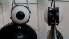
To make the cover to the target design turned out to be easy: I took a table tennis ball and cut it in half, I dont have a 14mm drill and doing the hole with a scalpel wasnt as nice a finish as a 15mm dremal sanding bit.
This cover was then glued over the front of the tweeter. The directivity went up in line with theory. The numbers looked good but it didnt sound right.
I didnt find any distortion or resonances from the cover but I found a significant issue with group delay and a peak at the frequency and magnitude coincident with the dipole D distance. I imagine the high directivity and wave guiding spherical shape combined to ensure the rear wave was able to come around to the front at a level that was not prefered.
Doubt a NEO would have the same issues though it should be trivial to increase the directivity with a piece of cardboard. .
A year or three ago I took a pair of very small Vifa OC25SC65-04 1"dome tweeters and glued them back to back to make a very small D dipole dome tweeter. The dipole SPL Vs frequency characteristic was in line with theory as was the directivity, dropping away off axis at higher frequency. I did the same with a similar ( though not as shallow) pair of Vifa 19mm tweeters and again the numbers measured matched the expected outcome.
These two prototypes didnt result in the constant constant directivity and 'full range dipole' I was seeking so I tried another experiment to make the emiting area smaller still.
I estimated that the small area would provide less SPL at the lower end of the tweeters range and set a target that balanced low frequency SPL capacity with directivity at 12,500Hz. My optima worked out to be a 14mm diameter. I played around with the design of a cover that would go over the 25mm tweeter to give me this size, I used the falstad ripple app and some basic theory to check for any downside of 1/4 wave or helmholz resonances and came up with a design that ensured these resonances were all out of range.
To make the cover to the target design turned out to be easy: I took a table tennis ball and cut it in half, I dont have a 14mm drill and doing the hole with a scalpel wasnt as nice a finish as a 15mm dremal sanding bit.
This cover was then glued over the front of the tweeter. The directivity went up in line with theory. The numbers looked good but it didnt sound right.
I didnt find any distortion or resonances from the cover but I found a significant issue with group delay and a peak at the frequency and magnitude coincident with the dipole D distance. I imagine the high directivity and wave guiding spherical shape combined to ensure the rear wave was able to come around to the front at a level that was not prefered.
Doubt a NEO would have the same issues though it should be trivial to increase the directivity with a piece of cardboard. .
Attachments
- Status
- This old topic is closed. If you want to reopen this topic, contact a moderator using the "Report Post" button.
- Home
- Loudspeakers
- Multi-Way
- Dipole Tweeter Waveguide