Hello there!
I have done a search but couldn't find this topic.
I am trying to understand the way the resistor and capacitor values are calculated for impedance correction (Zobel) for two bass/midrange units wired in parallel.
I do understand that two units in parallel effectively halves the impedance and inductance that the crossover 'sees'.
But each drive unit still has its individual characteristics which cause the impedance to rise and each unit might want to 'see' R-C values based on its own single specification.
So I can't work out whether the the R-C values need to calculated on the paralleled values of inductance and impedance or on the actual values of each individual unit.
Any guidance gratefully received.
There is always the old fashion way. Trial and error. I do the calculations, but they are never close. Mostly because Le is horribly difficult to measure. So, I throw something on there and use good old WT2 to measure. Fiddle till happy. My end results often suggest an effective Le under load as much as three times off published. Measure. Think, change, measure, think some more. The only true road to enlightenment.
Sorry, boys, I don't think either of your explanations is at all comprehensible to a normal human being. 
You calculate the Zobel for each individual bass/mid driver:
Impedance Equalization (L-Pad) Circuit Designer / Calculator
When you then parallel the two (identical) drive units, you will want to parallel the Zobels too. The result is the capacitance doubles and the resistance is halved over a Zobel for a single bass/mid.
So, for example, if a 6 ohm driver with an inductance of 0.6mH gives a Zobel of 7.5 ohms and 10.67 uF, two in parallel need 3.75 ohms and 21.33 uF.
4 ohms and 20 uF or 22uF would be near enough in practise in this case. They are kind of rough and ready in reality. You'd probably use a 10W wirewound resistor.
Agree, you CALCULATE it that way. All I am saying is that when you build it and measure the results, my experience has shown it to be WAY off. Why? Because you can't measure Le correctly. Calculate, but verify.
Good point, you don't need to be splitting hairs. Close is good enough.
Good point, you don't need to be splitting hairs. Close is good enough.
Sorry,system 7,but calculator programs such as the the one referenced do not provide the correct results and as tvrgeek is finding can be well out.Since the voice coil inductance,Le, is a variable a more arduous measuring procedure is required to measure it and Re at the the desired crossover frequency.I use a Grutzmacher Bridge as one method of obtaining the impedance and the phase angle that allow the correct values to be calculated.There are other methods and in particular if you have an impedance plot(graph) of your speaker together with its phase you can derive the values from this.Going one step further on this subject is for me to question why on earth the network should be considered a Zobel.Electrical engineering uses power factor correcting ccts to obtain a resistive load of the desired value.This is what I do and it is always spot on;whereas the Zobel corrections from sources starting from over 40 years ago are rarely anywhere near the correct value.
So, I throw something on there and use good old WT2 to measure. Fiddle till happy.
Ditto
Cheers,
Terry
I find Zobels work as advertised and calculated with woofers, actually.
It's not surprising since Le is usually measured at 1kHz. Re is quite well behaved too.
I'm sure yestor does not want to buy a Grutzmacher Bridge, or spend time reading Edward Norton, Steen Duelund, Marshall Leach or the original radio frequency constant resistance Zobel filters, AS I AND YOU DO. We are sad geeks, after all. He wanted a simple answer to a simple question.
Zobels are a bit of a fudge, of course. Even the name is not really correct, but in audio parlance we all understand they are a simple RC network which conjugates the RL loudspeaker component to give a reasonably flat load. Tweeters seem to go more astray due to the lossiness of loudspeaker voice coils at high frequencies. I find you halve the Cz value and up the resistance by about 25% from calculated values and it zobels along quite happily. You may not even need one with ferrofluid, of course.
The other consideration is that Zobels and a rolloff capacitor with woofers are often best replaced with a single capacitor and, say, a 2 ohm resistor. Much more economical and does much the same thing.
Yup, they work as advertised if you have the correct values to work from. Those correct values are what we are questioning. Quite right on the economical implementation, but network simplification is a couple steps above this conversation.
Le is typically at 1K, glued in place, which is why it is a tad difficult for us to measure. Not even going to touch eddy currents and everything else going on in the motor that makes it non-linear with power. In case anyone has a DVM that measures inductors, nope, won't work. Some measurement systems like SoundEasy will attempt to calculate it. The few I have done were maybe closer than published, but still way off. It does vary a lot vendor to vendor.
If anyone is having difficulty understanding how components add up, I recommend playing with it in SPICE. Really cheap way to experiment and you will get accustomed to think in both voltage and phase.
In the spirit of diyAudio,a Gruzmacher bridge is an easily constructed item.Junk box parts really.You need a c.t audio transformer,a three position switch,two precision resistors,a suitable potentiometer(precision 10 turn type with a dial) or a decade resistance box,terminals and a case. Auxillary equipment to perform useful measurements are an audio oscillator, a.c.millivoltmeter and for accuracy a freq. counter.See,"Sound System Engineering" by Don and Carolyn Davis.I have been reminded,by way of a private communication,(rebuke, in fact) that the accepted name for a power factor correction network is a Boucherot cell. It should be understood that the impedance and phase should be measured at the desired crossover frequency which is most likely not at 1kHz.
Last edited:
This is for everyone except sreten (who is not interested).
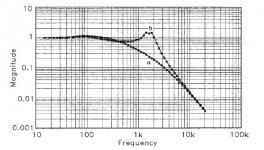
Here's Marshall Leach's calculation of the benefits of a Zobel with a standard LC bass filter.
Nice.
Here's Marshall Leach's calculation of the benefits of a Zobel with a standard LC bass filter.
An externally hosted image should be here but it was not working when we last tested it.
Nice.
Attachments
The graph that is shown originates from a JAES paper which may be read via users.ece.gatech.edu/mleach/papers/zobel.pdf. Power factor correction is a more practical implementation ,providing the values of Le and Re are measured (which should include the phase angle)at the desired xover frequency and the requisite calculations for the compensation network performed.The latter is definitely not the usually cited formula or what you find on calculator programs.However sreten is correct in stating that 'we' have strayed away from the OP query.Perhaps when he has finished brushing up on his alternating current theory in his old text books,he might provide more information.
Thank you VaNarn, I would support using Ztphase to help in breaking through this issue.
Directly on topic, the difference between compensating the woofers independently will be relatively insignificant. Staying on the electrical side for a moment if you did them separately, then merged the two (put the whole lot in parallel, drivers, caps, resistors and crossover inductors) you'd have the same net corrected driver impedance, the same net filter action. It comes down to the drivers sharing the signal if their impedance is different, and providing the acoustic response if that is different.
Usually these things are accepted, their differences are not normally large and are not normally something that sounds bad.
Yes,AllenB,whatever compensation is used,it is only intended to correct the phase and impedance to make the bass/mid speaker appear as a pure resistance for a crossover network to work at its design frequency and cut-off slope.By example a constant resistance network (say 8 Ohm) ,properly implemented will show a flat 8 Ohm impedance throughout the crossover region and not the broad impedance rise commonly seen.In a two way system with a dome tweeter,which is typically resistive (zero degrees phase) at 3kHz,the design is simplified as far as the xover goes,as only the sensitivities remain to be matched .
- Status
- This old topic is closed. If you want to reopen this topic, contact a moderator using the "Report Post" button.
- Home
- Loudspeakers
- Multi-Way
- Zobel network for parallel drive units