Here is a project that never got off the ground; although bought some Vifa ring tweeters recently and think this will work nicely with a proper crossover.
Woofer is Peerless 832591, 4ohm (old but never used and have a couple of backups).
Vifa ring XT25TG30-04 tweeter
Vifa XT25TG30-04 1" Dual Ring Radiator Tweeter 264-1016
The box is 1/3 cf and tuned as recommend.
We built several similar boxes with Morel MDT30s, 6db, .69mh coil, 3.3cap and L pad; 3.3 seems low, but it did crossover well at 1500hz-2000hz.
Woodworker here, could build crossover with design/plans.
Any ideas?
Attachments
Last edited:
A few thought to add:
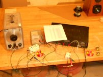
Will add 4 wire cable into boxes, then can work on crossover outside the box.
Tweeter SPL: 91.1
Woofer SPL: 88.8
Again, both 4 ohm
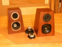
The little woofers have great bass for 5.25". The dust cap were removed and foam plugs were glued on the pole (magic tricks).
The boxes were lined with layers of spay glue and sand - thick!
Will add 4 wire cable into boxes, then can work on crossover outside the box.
Tweeter SPL: 91.1
Woofer SPL: 88.8
Again, both 4 ohm
The little woofers have great bass for 5.25". The dust cap were removed and foam plugs were glued on the pole (magic tricks).
The boxes were lined with layers of spay glue and sand - thick!
Last edited:
Not much info on it... although they were popular back in the day. I still have a few going here. What I did find was on here:
SCOTT'S HOMEPAGE
I (re)simed it in WinIsd, and I think I have the right box/port.
Love the tweeters! Using one in a center channel now. I pretty sure it would need a 12db roll off, that's what Madisound did with the HDS kit. (Pic)
SCOTT'S HOMEPAGE
I (re)simed it in WinIsd, and I think I have the right box/port.
Love the tweeters! Using one in a center channel now. I pretty sure it would need a 12db roll off, that's what Madisound did with the HDS kit. (Pic)
Attachments
Jeez! What am I supposed to be looking for here, mate?
SCOTT'S HOMEPAGE
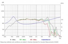
So far I have worked out this is a polycone with a highish inductance similar to the 8 ohm version known as a Peerless 832592. Seems to rolloff naturally around 4kHz with a bit of a peak there. Qts around 0.4 and VAS around 11 litres. Le of 8 ohm version is 1.1mH, which means this one could be 0.55mH to 1.1mH.
Best you can do is add a coil to the woofer, around voicecoil inductance in value, and wire and pad the tweeter out of phase on a second order, maybe 3.3uF or 4.7uF and 0.2mH. You'll need to do some work padding the Vifa tweeter itself too, since it's only 3 ohms Re. This gives you a good chance of some reasonable phase alignment, even if you get a lot of woofer cone breakup coming through.
You only have any chance of getting this to work at all because your cabinet is nearly time aligned.
SCOTT'S HOMEPAGE
So far I have worked out this is a polycone with a highish inductance similar to the 8 ohm version known as a Peerless 832592. Seems to rolloff naturally around 4kHz with a bit of a peak there. Qts around 0.4 and VAS around 11 litres. Le of 8 ohm version is 1.1mH, which means this one could be 0.55mH to 1.1mH.
Best you can do is add a coil to the woofer, around voicecoil inductance in value, and wire and pad the tweeter out of phase on a second order, maybe 3.3uF or 4.7uF and 0.2mH. You'll need to do some work padding the Vifa tweeter itself too, since it's only 3 ohms Re. This gives you a good chance of some reasonable phase alignment, even if you get a lot of woofer cone breakup coming through.
You only have any chance of getting this to work at all because your cabinet is nearly time aligned.
Last edited:
Hi,
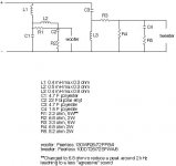
Might be a good place to start or sim from, from a swedish kit.
But then again not, doesn't look like it has much baffle step,
I don't like the 2.2R in series with the bass mid, that might
be there to boom up the bass due to the lack of BSC.
Here is the 8 ohm version :
http://www.parts-express.com/pdf/297-622.pdf
rgds, sreten.
Attachments
Last edited:
Wow crazy...I'm going for it.
Have some of the parts here, will order the rest. I'm not versed in Bi polar F ellyt or poyester caps only the polypropylene (look like firecrackers).
I'm guessing they are the smaller ones that don't cost a kings fortune.
(a friend did find a way to wind/modify coils with a good deal of accuracy)
Amazing - Thanks!
I done something similar here with full BSC but 8 ohms woofer.
http://www.diyaudio.com/forums/multi-way/190225-hi-vi-m6a-vifa-xt25tg30.html#post2594710
For 4 ohms the woofer L1=1mH (0.5...1mH can work, depend on the part you have, just adjust the tweeter level)
The peak was 3K instead 4K . For 4K
Lz1 = 0.4mH
Cz1 = 4uF
Rz1 = 6.8 ohms
You can also keep the crossover of the sweden kit for the tweeter if you have the components, my tweeter crossover is similar.
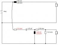
I'd GUESS looking at Thomas Akerlund's circuit there, that the 4 ohm peerless has Le of 0.55mH...
So this looks reasonable to me as a start:
The 0.1 ohm resistor is adjustable for tweeter level. The 0.55mH coil will mean there isn't much bafflestep correction, so these are best placed by a wall. Think that agrees with Jerome69's ideas too. Really can't say how bad the woofer peaks are going to sound, or exactly how to tame them. But this circuit is non-critical and has good phase alignment from 2kHz to 10kHz.
So this looks reasonable to me as a start:
An externally hosted image should be here but it was not working when we last tested it.
The 0.1 ohm resistor is adjustable for tweeter level. The 0.55mH coil will mean there isn't much bafflestep correction, so these are best placed by a wall. Think that agrees with Jerome69's ideas too. Really can't say how bad the woofer peaks are going to sound, or exactly how to tame them. But this circuit is non-critical and has good phase alignment from 2kHz to 10kHz.
Attachments
As you can see, it is more important to look clever at this forum, than to explain yourself clearly.
")
An externally hosted image should be here but it was not working when we last tested it.
None of the values in this circuit are actually critical. The coils/inductors have standard DC resistance (aka DCR to the initiated...) due to copper windings of several metres. Any air coil will be close to these (0.3 or 0.4 ohm) resistances. Ferrite coils will be better, but not usually used in tweeter positions.
The top woofer coil can be 0.4-0.7mH, the tweeter coil 0.4-0.7mH. The capacitor can be 3.3 or 4.7 uF non-polar or polycap. The 10 ohm can be 8.2 ohm. The 3 ohm anything between 2 and 4 ohm for test purposes. You are going to set tweeter level with the 0.1 ohm resistor later, which is a place marker, not a value.
Bit meaningless to talk about rolloff. Ultimately it's 24dB for the woofer. This is really a first order circuit with a bit of protection added to the tweeter by the 0.4mH coil at it's Fs resonance which is about 900Hz I'd guess.
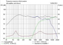
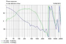
You can expect a response a bit like the below diagrams with a 3.3 attenuation resistor in place on the tweeter. But that has to be done by ear. It's all pure guesswork really, but helped by your near time alignment.
You can expect a response a bit like the below diagrams with a 3.3 attenuation resistor in place on the tweeter. But that has to be done by ear. It's all pure guesswork really, but helped by your near time alignment.
Attachments
- Status
- This old topic is closed. If you want to reopen this topic, contact a moderator using the "Report Post" button.
- Home
- Loudspeakers
- Multi-Way
- 2 way crossover design help