Hello,
***First i want to say I'm not sure if i should post this under Fullrange or Multiway. Since at this point, there is a high posibility of the need for a supertweeter i chose Multiway forums. I won't mind tho if moderators think it's more suited for Fullrange forums.
About 6 months ago, i started thinking about a DIY fieldcoil speaker. I know opinions vary quite a lot on this matter and so i will do my best to offer as much data as possible for things to be judged objectively. Since that time I have been talking with some fellow countrymen and audio enthusiasts about this project and these conversations helped me in making some of the design decisions. The work is still in progress and i hope your opinions and comments can help tune it to higher performance.
To begin, here are the basic aspects about this project:
- field coil underhung motor structure
- 12" diameter
- Wide range (up to 10kHz), hopefully fullrange (up to 20kHz)
- high efficiency
- to be used in BLH
My personal taste in sound is that i like it when it comes out of large radiating surfaces. Large SD, large horn mouths etc. I think it's a necesity when one tries to reach real, live music levels and at the same time keep a good response to instruments' attack, sustain and decay. This is the reason i chose 12 inch diameter. I would've liked 15" better but it would've been too difficult to make it wide range. Perphaps a future project.
Field Coil Motor Structure:
I have spent a lot of time looking for other field coil projects, for any information on FC design or about available products and i have to say there isn't
much out there. From the pictures of opened FC units i could see a basic shape of the pole pieces. I have to say this is amongst the first design issues i encountered, there isn't much freedom to design these pole pieces, not like the case with permanent magnets anyway.
The next thing one can notice is that the new FCs are low impedance type and this is easily understandable. I have decided that my field coil will also work with 12-15V supply.
Underhung design means thick top plate. Of course this will cause a drop in flux density in the gap. The compromise here i found to be between flux density value and voice coil excursion. Since this speaker will mostly be used horn loaded i sacrificied Xmax to make a thinner top plate. I use standard 1010 steel with a maximum of 0.13% carbon, the best i could get my hands on.
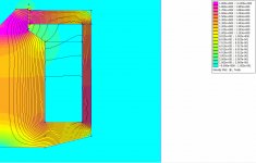
I ran simmulations in FEMM for different values of top plate thickness, FC's number of turns, dimension, wire diameter etc. Here are the results i stopped at:
- magnetic gap height: 12mm
- magnetic gap width: 1-1.5mm
- 5.3 ohm FC 1400 turns of 1.25mm copper wire
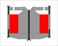
Below you can find a rather crude sketch of motor structure:

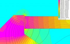
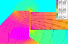
Here are some results from FEMM analysis:
I ran simmulations with 1010 steel as well as 416 steel (has slightly more carbon typical 0.15%) to see the differences.


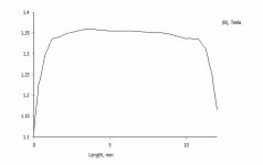
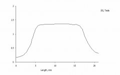
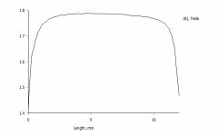
1010 Steel Curve over 20mm and 12mm:


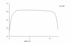
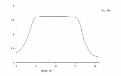
416 Steel Curve over 20mm and 12mm: (actually the curves are smoother had to lower resolution a bit because of my computer)


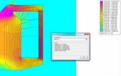
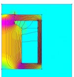
Magnetic gap:

AS it is, at 2.2 Amps we have 25W for the FC. I don't expect to have too much trouble with heat at this power. Test will tell tho, depending on how well the metal does the job of sinking the heat. The value predicted by FEMM lies around 1.6 Tesla. In reality i believe this value will be smaller 1.4-1.5 T. In tests i will drive the FC with 3 amps and see how much it heats up.
In this design the gap width is 1.5mm. Somewhat large, I'm thinking to add a 0.5mm thick copper ring right in the gap (yellow part from picture below). Now
it's true i have never seen a picture with a FC unit having a faraday ring and I'm not sure if it's necesary. I guess the FC itself has a role in that too.

I'm also making a 1mm gap variant (without copper ring) in hopes to get more flux density. The FEMM simmulation shows:


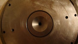
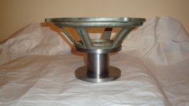
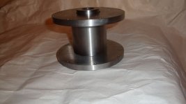
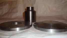
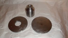
Here are some parts of the magnetic structure after machining:


***First i want to say I'm not sure if i should post this under Fullrange or Multiway. Since at this point, there is a high posibility of the need for a supertweeter i chose Multiway forums. I won't mind tho if moderators think it's more suited for Fullrange forums.
About 6 months ago, i started thinking about a DIY fieldcoil speaker. I know opinions vary quite a lot on this matter and so i will do my best to offer as much data as possible for things to be judged objectively. Since that time I have been talking with some fellow countrymen and audio enthusiasts about this project and these conversations helped me in making some of the design decisions. The work is still in progress and i hope your opinions and comments can help tune it to higher performance.
To begin, here are the basic aspects about this project:
- field coil underhung motor structure
- 12" diameter
- Wide range (up to 10kHz), hopefully fullrange (up to 20kHz)
- high efficiency
- to be used in BLH
My personal taste in sound is that i like it when it comes out of large radiating surfaces. Large SD, large horn mouths etc. I think it's a necesity when one tries to reach real, live music levels and at the same time keep a good response to instruments' attack, sustain and decay. This is the reason i chose 12 inch diameter. I would've liked 15" better but it would've been too difficult to make it wide range. Perphaps a future project.
Field Coil Motor Structure:
I have spent a lot of time looking for other field coil projects, for any information on FC design or about available products and i have to say there isn't
much out there. From the pictures of opened FC units i could see a basic shape of the pole pieces. I have to say this is amongst the first design issues i encountered, there isn't much freedom to design these pole pieces, not like the case with permanent magnets anyway.
The next thing one can notice is that the new FCs are low impedance type and this is easily understandable. I have decided that my field coil will also work with 12-15V supply.
Underhung design means thick top plate. Of course this will cause a drop in flux density in the gap. The compromise here i found to be between flux density value and voice coil excursion. Since this speaker will mostly be used horn loaded i sacrificied Xmax to make a thinner top plate. I use standard 1010 steel with a maximum of 0.13% carbon, the best i could get my hands on.
I ran simmulations in FEMM for different values of top plate thickness, FC's number of turns, dimension, wire diameter etc. Here are the results i stopped at:
- magnetic gap height: 12mm
- magnetic gap width: 1-1.5mm
- 5.3 ohm FC 1400 turns of 1.25mm copper wire
Below you can find a rather crude sketch of motor structure:
Here are some results from FEMM analysis:
I ran simmulations with 1010 steel as well as 416 steel (has slightly more carbon typical 0.15%) to see the differences.
1010 Steel Curve over 20mm and 12mm:
416 Steel Curve over 20mm and 12mm: (actually the curves are smoother had to lower resolution a bit because of my computer)
Magnetic gap:
AS it is, at 2.2 Amps we have 25W for the FC. I don't expect to have too much trouble with heat at this power. Test will tell tho, depending on how well the metal does the job of sinking the heat. The value predicted by FEMM lies around 1.6 Tesla. In reality i believe this value will be smaller 1.4-1.5 T. In tests i will drive the FC with 3 amps and see how much it heats up.
In this design the gap width is 1.5mm. Somewhat large, I'm thinking to add a 0.5mm thick copper ring right in the gap (yellow part from picture below). Now
it's true i have never seen a picture with a FC unit having a faraday ring and I'm not sure if it's necesary. I guess the FC itself has a role in that too.
I'm also making a 1mm gap variant (without copper ring) in hopes to get more flux density. The FEMM simmulation shows:
Here are some parts of the magnetic structure after machining:
Attachments
-
 FC_Structure01.jpg623 KB · Views: 525
 -
 FC_1mm_gap.jpg190.1 KB · Views: 371
 -
 FC_Field_gap_LC_2_2Amp.jpg174 KB · Views: 327
 -
 Gap_faraday.jpg28.5 KB · Views: 332
 -
 FC_B_hC_2_2Amp_12mm.jpg41.3 KB · Views: 317
 -
 FC_B_hC_2_2Amp_20mm.jpg39.7 KB · Views: 344
 -
 FC_B_LC_2_2Amp_12mm.jpg40.3 KB · Views: 319
 -
 FC_B_LC_2_2Amp_20mm.jpg41.7 KB · Views: 342
 -
 FC_Field_LC_2_2Amp.jpg185.2 KB · Views: 373
 -
 FC_Field_hC_2_2Amp.jpg199 KB · Views: 439
Last edited:
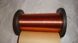
Voice Coil:
Voice coil is 2" diameter. Haven't decided on the former material yet, and there is still some designing work to be done. I will use 0.13mm copper-clad aluminum wire (hoping to receive it Monday).
Data for the ECCA wire is as follows:
Copper Vol: 15-17%
Density [g/ccm]: 3.7
Resistivity [ohm*sqmm/m]: 0.0255
I will come back to the voice coil issue soon.
Cone:
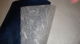
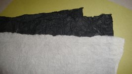
Cone will be made of japanese paper called washi (fullrange crowd might now why hehe). I got a few rolls of washi of different types and will test a few variants.


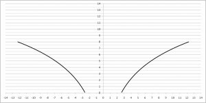
Next week work will start on cones, most probably will be made from 12 petals. I will test both straigth and curved cone. An exponential curved profile like in the picture below has a calculated flare rate of 0.387/cm which should correspond to a freq close to 1050Hz. Have to look into whizer cone as well.

Thats it for now, let me know what you think so far. I will post more info as i go with this project. I hope it will awake more interest into fieldcoils and
shed some light on the matter.
Voice coil is 2" diameter. Haven't decided on the former material yet, and there is still some designing work to be done. I will use 0.13mm copper-clad aluminum wire (hoping to receive it Monday).
Data for the ECCA wire is as follows:
Copper Vol: 15-17%
Density [g/ccm]: 3.7
Resistivity [ohm*sqmm/m]: 0.0255
I will come back to the voice coil issue soon.
Cone:
Cone will be made of japanese paper called washi (fullrange crowd might now why hehe). I got a few rolls of washi of different types and will test a few variants.
Next week work will start on cones, most probably will be made from 12 petals. I will test both straigth and curved cone. An exponential curved profile like in the picture below has a calculated flare rate of 0.387/cm which should correspond to a freq close to 1050Hz. Have to look into whizer cone as well.
Thats it for now, let me know what you think so far. I will post more info as i go with this project. I hope it will awake more interest into fieldcoils and
shed some light on the matter.
Attachments
-
 DSC02863.JPG366.5 KB · Views: 469
 -
 DSC02858.JPG334.5 KB · Views: 464
 -
 DSC02867.JPG403.7 KB · Views: 268
 -
 DSC02866.JPG348.2 KB · Views: 244
 -
 DSC02864.JPG339.3 KB · Views: 263
 -
 cone contour.jpg80.3 KB · Views: 280
 -
 DSC02857.JPG315.1 KB · Views: 280
 -
 DSC02854.JPG241.6 KB · Views: 297
 -
 DSC02849.JPG244 KB · Views: 300
 -
 FC_1mm_gap_B_high_res.jpg40 KB · Views: 282
Wow, Hentai, this is great.. I and a number of other members have been waiting forever for someone with the requisite skill set to bring a FC speaker project to the forum.
I think Pano will be equally interested in your project.
Probably a bit beyond my current machining skill set, but I will be following avidly.
I think Pano will be equally interested in your project.
Probably a bit beyond my current machining skill set, but I will be following avidly.

Hello, glad you find the topic interesting.
Yes, a high BL is mandatory for high efficiency. I am also looking to tilt the response upwards in frequency, as in higher sensitivity while going up in band. This will be very helpful when using horn loading.
Of course electromagnetic overdamping will be an option on how hot you run the FC.
But as you identified, i aim to get 1.4T and not overheat the FC.
I will post later about Voice coil and its part in the BL figure. A high length of wire makes a high BL but also increases mass and i want to keep mass as low as possible for efficiency and wide bandwidth. However i made some calculations on how much i gain either by increasing BL and mass alltogether or reducing BL and mass as well. I will post them later after some checking. BL on its own doesn't say the whole story there is also the issue of DC resistance of wire that i will touch on later as well.
I have a similar project going. It's been muffballed lately though, due to time constraints.
I have made a motor similar to yours.
I have opted for 6.5", but with a +/-5mm excursion, to get the full spectrum.
The only way as I see it, to get up to 20kHz, is to make a light and stiff cone.
My solution to this, has been to go the composite route.
I have currently made molds for the spider, the surround, the VC, the phase plug is also made, and the mold for the cone. Lacking so far is a suitable basket, and a couple of days work.
Thanks for posting your project, it sure is interesting, and you seem to have the skills required to pull this off.
Magura
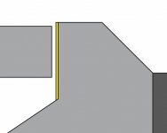
The reason for this basic shape of the magnetic structure, as i can understand it, is that the middle pole piece, the core of the field coil saturates very easily. It has to be very thick. Mine is 80mm in diameter and the shrinks to create the magnetic gap.
In the rest of the circuit i looked out for signs of saturation but also didnt want to add too much iron because of cost and weight. Below is a picture with the bottom plate thinner and flat. You can see there is trouble there so i made the common truncated cone shape.

More on Voice Coil:
The magnetic gap is 12mm in height and this is the VC's height limitation as well. At first i was looking into a 9 mm height vc but the xmax figure was unacceptable. A thinner wire tho allows me to reduce the height to 6 mm to give the theoretical +/- 3mm of excursion. I made the pole piece 1 mm above the top plate to make a more gentle slope on curve in case this excursion is exceeded. Now i think it could've been 2mm as well or maybe better.
When calculating the voice coil parameters at first i was obsessed with low mass. I was even thinking of a single layer of such thin wire if it was possible. It presented too many issues tho both electrical and mechanical.
With a single layer i would have a small BL value, high DCR and the voice coil would be too fragile for a 12 incher.
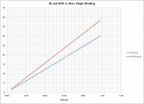
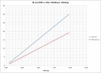
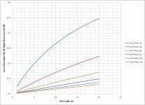
So i wondered with such a thin wire how much mass can i save by not going multilayer? It turns out that gain in mass has a too small effect on efficiency compared to the increase in BL.
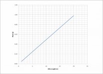
Of course one needs to consider this gain in mass in addition to the cone mass. The chart bellow compares the two efficiency values for different cone mass. As you can see the cone has to be very very light, has to have a mass very close to that of the wire to make a difference. Once the weight lies mostly in the cone its best to put as much wire as possible in order to get high BL.

One more aspect i needed to clear. The actual motor force figure. DCR opposes current so it's not enough to have a high BL i needed to factor in DCR. Looking at efficiency formula the figure [BL^2/Re] stands out. And it makes sense as this figure is the actual motor strength figure. This is a constant for every loudspeaker even the ones with dual voice coils. In dual voice coils BL can change depending on how you wire the coils but Bl^2/Re remains constant.
Considering all this i came to a 16ohm nominal voice coil made from 2 paralel coils of 14.6m each. One can eliminate the parallel windings by using thicker wire.
6mm Hvc
Zn---Len---Rdc---Obs--------------BL------Mass---BL^2/Rdc
16---7.33--14.09--Single layer------10.995--0.36---8.580303971
8----7.33--7.04---2 Layer Parallel---10.995--0.72---17.16060794
16---14.6--14.09--4 Layer 2 S 2 P---21.99---1.44---34.32121588
Bellow are some charts i made when doing calculations for this specific 0.13mm ECCA wire.


In the rest of the circuit i looked out for signs of saturation but also didnt want to add too much iron because of cost and weight. Below is a picture with the bottom plate thinner and flat. You can see there is trouble there so i made the common truncated cone shape.
More on Voice Coil:
The magnetic gap is 12mm in height and this is the VC's height limitation as well. At first i was looking into a 9 mm height vc but the xmax figure was unacceptable. A thinner wire tho allows me to reduce the height to 6 mm to give the theoretical +/- 3mm of excursion. I made the pole piece 1 mm above the top plate to make a more gentle slope on curve in case this excursion is exceeded. Now i think it could've been 2mm as well or maybe better.
When calculating the voice coil parameters at first i was obsessed with low mass. I was even thinking of a single layer of such thin wire if it was possible. It presented too many issues tho both electrical and mechanical.
With a single layer i would have a small BL value, high DCR and the voice coil would be too fragile for a 12 incher.
So i wondered with such a thin wire how much mass can i save by not going multilayer? It turns out that gain in mass has a too small effect on efficiency compared to the increase in BL.
Of course one needs to consider this gain in mass in addition to the cone mass. The chart bellow compares the two efficiency values for different cone mass. As you can see the cone has to be very very light, has to have a mass very close to that of the wire to make a difference. Once the weight lies mostly in the cone its best to put as much wire as possible in order to get high BL.
One more aspect i needed to clear. The actual motor force figure. DCR opposes current so it's not enough to have a high BL i needed to factor in DCR. Looking at efficiency formula the figure [BL^2/Re] stands out. And it makes sense as this figure is the actual motor strength figure. This is a constant for every loudspeaker even the ones with dual voice coils. In dual voice coils BL can change depending on how you wire the coils but Bl^2/Re remains constant.
Considering all this i came to a 16ohm nominal voice coil made from 2 paralel coils of 14.6m each. One can eliminate the parallel windings by using thicker wire.
6mm Hvc
Zn---Len---Rdc---Obs--------------BL------Mass---BL^2/Rdc
16---7.33--14.09--Single layer------10.995--0.36---8.580303971
8----7.33--7.04---2 Layer Parallel---10.995--0.72---17.16060794
16---14.6--14.09--4 Layer 2 S 2 P---21.99---1.44---34.32121588
Bellow are some charts i made when doing calculations for this specific 0.13mm ECCA wire.
Attachments
<snip>
I have opted for 6.5", but with a +/-5mm excursion, to get the full spectrum.
The only way as I see it, to get up to 20kHz, is to make a light and stiff cone.
My solution to this, has been to go the composite route.
I have currently made molds for the spider, the surround, the VC, the phase plug is also made, and the mold for the cone. Lacking so far is a suitable basket, and a couple of days work.
Hello Magura,
I'm glad you joined this thread, i read about your project on Zen Mod's forum.
Indeed, i too, place a high importance on low mass and i hope petals will make my cone rigid. So far i haven't done much work on suspension system. My goal is a fs around 50hz with a Mmd of 24g. But i will clear on this next week most probably. Im making a tool to help me create the cone and i can estimate a mass value then.
Keep in touch.
-Andrei


Hi Hentai,
I enjoyed reading your field coil education. Constructing an execeptional cone, surround, and suspension has driven many engineers mad, so stock up on good California red wines now.
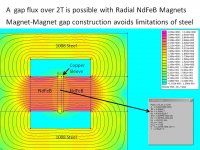
It is possible to construct an underhung radial NdFeB speaker motor with over 2T gap flux by using a magnet-to-magnet topology across the gap. When one works through the total T/S parameter requirements for an optimum speaker+cabinet, this high gap flux creates a very low Qts which typically requires horn loading to get extended bass, or at least a 4-way design to compensate for the limited driver bandwidth. The engineer has to balance efficiency vs. bandwidth vs. cabinet effects(like high phase delays from horns).
Do you have personal experience with beaming/lobing effects from using a 12" full range? Controlled directivity speakers which use a high efficiency 12" midbass typically cross over to a 90x40degree horn at 900Hz or a 60x40 degree horn at 1200Hz. The Levinson Daniel Hertz is one example of how a high efficiency 12" is used with controlled directionality 60x40 horn tweeter. Do you have any back up plans that use your 12" speaker in a 3-way design?
I enjoyed reading your field coil education. Constructing an execeptional cone, surround, and suspension has driven many engineers mad, so stock up on good California red wines now.
It is possible to construct an underhung radial NdFeB speaker motor with over 2T gap flux by using a magnet-to-magnet topology across the gap. When one works through the total T/S parameter requirements for an optimum speaker+cabinet, this high gap flux creates a very low Qts which typically requires horn loading to get extended bass, or at least a 4-way design to compensate for the limited driver bandwidth. The engineer has to balance efficiency vs. bandwidth vs. cabinet effects(like high phase delays from horns).
Do you have personal experience with beaming/lobing effects from using a 12" full range? Controlled directivity speakers which use a high efficiency 12" midbass typically cross over to a 90x40degree horn at 900Hz or a 60x40 degree horn at 1200Hz. The Levinson Daniel Hertz is one example of how a high efficiency 12" is used with controlled directionality 60x40 horn tweeter. Do you have any back up plans that use your 12" speaker in a 3-way design?
Attachments
Hello LineSource,
Yes the mechano-acoustic part of the loudspeaker is the hardest to make. The phenomenons are too complicated to predict accurately. Red wine sure comes in handy.
Depending on final Mmd i want Qes between 0.15 to 0.25. The overdamped motor coupled with the low Mmd should result in a sensitivity rise with increasing frequency. In a bass reflex alignment you will need to lower the current through the field coil to achieve a better tonal balance. In horn however this tilt in response can be extremely beneficiary, especially in a FLH and BLH (kinda like the Westminster), as it will lift the lower sensitivity of low and mid band to match the high frequency instead of just using xover to cut the high band.
There is much to be said about beaming and about whizzer's role in the whole picture. There isnt much data on the development of these components either. But lots of opinions and tested units. In a few hours when i will get home i will post some simulations results. I used Axidriver to try and simulate beaming of the cone. Unfortunately there is no option to add whizzer cone so i made separate simulation. Of course the issue of combining the two is another problem in itself.
You can get high flux density with neo magnets but its pretty hard to work with pre-magnetized neo and metal parts
Yes the mechano-acoustic part of the loudspeaker is the hardest to make. The phenomenons are too complicated to predict accurately. Red wine sure comes in handy
. Depending on final Mmd i want Qes between 0.15 to 0.25. The overdamped motor coupled with the low Mmd should result in a sensitivity rise with increasing frequency. In a bass reflex alignment you will need to lower the current through the field coil to achieve a better tonal balance. In horn however this tilt in response can be extremely beneficiary, especially in a FLH and BLH (kinda like the Westminster), as it will lift the lower sensitivity of low and mid band to match the high frequency instead of just using xover to cut the high band.
There is much to be said about beaming and about whizzer's role in the whole picture. There isnt much data on the development of these components either. But lots of opinions and tested units. In a few hours when i will get home i will post some simulations results. I used Axidriver to try and simulate beaming of the cone. Unfortunately there is no option to add whizzer cone so i made separate simulation. Of course the issue of combining the two is another problem in itself.
You can get high flux density with neo magnets but its pretty hard to work with pre-magnetized neo and metal parts
- Home
- Loudspeakers
- Multi-Way
- Project Ryu - DIY Field Coil Loudspeaker