Compression Driver
On another note, i mentioned i will be starting to play with compression driver. While it takes longer than expect, i am making some progress in this regard.
Guided by Henricksen's paper "Phase Plug Modelling and Analysis: Radial versus Circumferential Types" I made a spreadsheet to calculate the phase plug parameters. You can see it attached even tho its not really arranged but keep in mind only the blue cells are user inputs.
The excel shows data to draw the piece and also baffle input for AxiDriver. It shows only Reflector side so you will need to draw the baffle according to your compression driver's profile.
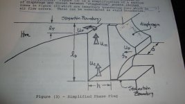
You will find attached o picture showing figure 3 from the paper. That is basically a section through the phase plug representing the acoustic path. The air trapped between the diaphragm and the phase plug has a volume and mass defined by length Ld and width (delta). Considering a 2 slit circumferential phase plug you can see how delta will vary for the 2nd slit as circumference will be higher.
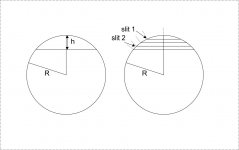
For the first phase plug i decided to keep this mass of air constant by keeping the diaphragm surface area acting on each slit constant. This is what the spread sheet will do . knowing that the surface area of a spherical segment is 2*pi*R*h with R being the radius and h the height between the upper and lower segment planes, we can see that we will satisfy the initial condition by splitting h in equal parts.
As you can see in the picture with the 2 circles, h was divided into 4 egual parts corresponding to the 4 acoustic paths in a 2 slit phase plug. The arc length between the dotted lines correspond to Ld. Keeping surface constant will cause Ld to vary, you see. According to Henricksen you can determine a cutoff frequency based on Ld and it states that f0=c/(3.63*Ld). How much will this apply to a varying Ld design will have to check experimentally.
At low frequency we know all the air will be pushed through the slits and at high frequency some it will just compress. Because of this the air has mass and compliance which can be modeled as inductance and capacitance. In the paper we have f0=1/(2*pi*sqrt(LC)) a known formula. When compared to the Ld based f0 something goes wrong as i dont think i interpret it correctly.
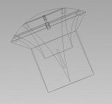
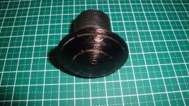
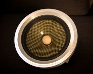
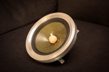
Anyways based on this i had my phase plug design parameters for a first try ready. There is one more thing that was on my mind. To me most of the circumferential slit phase plugs dont terminate smoothly. The slit throat grows to the point where it meets the other slits and then boom right into the large exit of compression driver. I thought i should have unite in pairs to make a smoother transition.
In this first try i didnt look for equal path lengths it is something i will try next.
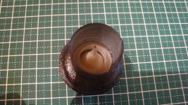
You can see from the pictures tho how the middle section extends to provide a smoother transition. How good it will be, if any? i will test it soon.
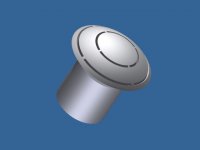
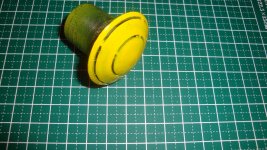
You can see some already made PPs, Need to smooth them out and put them in a driver.
On another note, i mentioned i will be starting to play with compression driver. While it takes longer than expect, i am making some progress in this regard.
Guided by Henricksen's paper "Phase Plug Modelling and Analysis: Radial versus Circumferential Types" I made a spreadsheet to calculate the phase plug parameters. You can see it attached even tho its not really arranged but keep in mind only the blue cells are user inputs.
The excel shows data to draw the piece and also baffle input for AxiDriver. It shows only Reflector side so you will need to draw the baffle according to your compression driver's profile.
You will find attached o picture showing figure 3 from the paper. That is basically a section through the phase plug representing the acoustic path. The air trapped between the diaphragm and the phase plug has a volume and mass defined by length Ld and width (delta). Considering a 2 slit circumferential phase plug you can see how delta will vary for the 2nd slit as circumference will be higher.
For the first phase plug i decided to keep this mass of air constant by keeping the diaphragm surface area acting on each slit constant. This is what the spread sheet will do . knowing that the surface area of a spherical segment is 2*pi*R*h with R being the radius and h the height between the upper and lower segment planes, we can see that we will satisfy the initial condition by splitting h in equal parts.
As you can see in the picture with the 2 circles, h was divided into 4 egual parts corresponding to the 4 acoustic paths in a 2 slit phase plug. The arc length between the dotted lines correspond to Ld. Keeping surface constant will cause Ld to vary, you see. According to Henricksen you can determine a cutoff frequency based on Ld and it states that f0=c/(3.63*Ld). How much will this apply to a varying Ld design will have to check experimentally.
At low frequency we know all the air will be pushed through the slits and at high frequency some it will just compress. Because of this the air has mass and compliance which can be modeled as inductance and capacitance. In the paper we have f0=1/(2*pi*sqrt(LC)) a known formula. When compared to the Ld based f0 something goes wrong as i dont think i interpret it correctly.
Anyways based on this i had my phase plug design parameters for a first try ready. There is one more thing that was on my mind. To me most of the circumferential slit phase plugs dont terminate smoothly. The slit throat grows to the point where it meets the other slits and then boom right into the large exit of compression driver. I thought i should have unite in pairs to make a smoother transition.
In this first try i didnt look for equal path lengths it is something i will try next.
You can see from the pictures tho how the middle section extends to provide a smoother transition. How good it will be, if any? i will test it soon.
You can see some already made PPs, Need to smooth them out and put them in a driver.
Attachments
-
 DSC04186.JPG96.9 KB · Views: 1,031
 -
 DSC_0116.jpg628 KB · Views: 1,039
 -
 Ryu Phase Plug CS.jpg35.8 KB · Views: 936
 -
 RYUPPCD02.jpg12.3 KB · Views: 932
 -
 DSC04183.JPG187.9 KB · Views: 921
 -
 DSC04155.JPG152.3 KB · Views: 313
 -
 DSC04160.JPG183.2 KB · Views: 320
 -
Project Ryu Compression Driver.zip12.3 KB · Views: 67
How do you insert tumbnails?
Take care,
when reply to thread, scroll down, and click on 'manage attachment', and find the picture in your file, click on it, and ...
sometimes you may need to scale down or reformat, etc ... which I did
and I also often choose to reframe, to remove what is not needed
it will then need less down scaling, and results in better upload
Attachments
Awesome speaker Jef. Congrats.
Pretty good bass i get from the video. Nice.
T/S i use WT3 and/or LIMP. With the later you can use a power amp for higher current but you need to make a little test rig. WT3 is very fast to get a impedance curve tho.
I assembled the cone for OB. Im waiting for glue to set in and will get it running pretty soon.
Cant wait to read/see the results..

On another note, i mentioned i will be starting to play with compression driver. While it takes longer than expect, i am making some progress in this regard.
Guided by Henricksen's paper "Phase Plug Modelling and Analysis: Radial versus Circumferential Types" I made a spreadsheet to calculate the phase plug parameters. You can see it attached even tho its not really arranged but keep in mind only the blue cells are user inputs.
The excel shows data to draw the piece and also baffle input for AxiDriver. It shows only Reflector side so you will need to draw the baffle according to your compression driver's profile.
You will find attached o picture showing figure 3 from the paper. That is basically a section through the phase plug representing the acoustic path. The air trapped between the diaphragm and the phase plug has a volume and mass defined by length Ld and width (delta). Considering a 2 slit circumferential phase plug you can see how delta will vary for the 2nd slit as circumference will be higher.
For the first phase plug i decided to keep this mass of air constant by keeping the diaphragm surface area acting on each slit constant. This is what the spread sheet will do . knowing that the surface area of a spherical segment is 2*pi*R*h with R being the radius and h the height between the upper and lower segment planes, we can see that we will satisfy the initial condition by splitting h in equal parts.
As you can see in the picture with the 2 circles, h was divided into 4 egual parts corresponding to the 4 acoustic paths in a 2 slit phase plug. The arc length between the dotted lines correspond to Ld. Keeping surface constant will cause Ld to vary, you see. According to Henricksen you can determine a cutoff frequency based on Ld and it states that f0=c/(3.63*Ld). How much will this apply to a varying Ld design will have to check experimentally.
At low frequency we know all the air will be pushed through the slits and at high frequency some it will just compress. Because of this the air has mass and compliance which can be modeled as inductance and capacitance. In the paper we have f0=1/(2*pi*sqrt(LC)) a known formula. When compared to the Ld based f0 something goes wrong as i dont think i interpret it correctly.
Anyways based on this i had my phase plug design parameters for a first try ready. There is one more thing that was on my mind. To me most of the circumferential slit phase plugs dont terminate smoothly. The slit throat grows to the point where it meets the other slits and then boom right into the large exit of compression driver. I thought i should have unite in pairs to make a smoother transition.
In this first try i didnt look for equal path lengths it is something i will try next.
You can see from the pictures tho how the middle section extends to provide a smoother transition. How good it will be, if any? i will test it soon.
You can see some already made PPs, Need to smooth them out and put them in a driver.
This might also contain some usefll information for you:
Patent US20040156519 - Phase plug with optimum aperture shapes - Google Patents
Good link Wim,
I approached phase plugs more from thoughts i had in mind for a long time rather than complete calculation.
For example in my personal experience the concave type of pp like in EV DH3 sound better. and i thought it might be because the transition between slit openings is smoother. One slit doesnt just end in the large diameter of the driver's exit but it will meet the other slit and the section still expands gradually to the exit.
This might mean nothing, because if you look at a line array arrangement then most phaseplugs are like that at their exits.
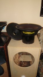
Anyways i got to play the high Qes cone. I put it on you tube cuz i listened Hugh Masekela - Stimela from Hope. Just the speaker not tweeter or drivers. On top is the midbass cone i removed.
Voice coil is a single layer 0.15mm ECW, 52mm diameter 6mm height. Rdc= 5.9 ohms. Qes = 0.9. Havent measured the cone's weight but its heavier about 30-35g to lower fs as well which is 37Hz
Some of my equipment is rented out so i had to come into sound card with balanced signal. Not sure what caused it but it picked up some noise. In that room i got not earth connection on mains so could be it. Even so, i think you can get a vast idea on its timbre.
Its not mounted on OB its in the reflex enclosure with the port stuffed shut.
https://www.youtube.com/watch?v=dWe4owHDIPM
I approached phase plugs more from thoughts i had in mind for a long time rather than complete calculation.
For example in my personal experience the concave type of pp like in EV DH3 sound better. and i thought it might be because the transition between slit openings is smoother. One slit doesnt just end in the large diameter of the driver's exit but it will meet the other slit and the section still expands gradually to the exit.
This might mean nothing, because if you look at a line array arrangement then most phaseplugs are like that at their exits.
Anyways i got to play the high Qes cone. I put it on you tube cuz i listened Hugh Masekela - Stimela from Hope. Just the speaker not tweeter or drivers. On top is the midbass cone i removed.
Voice coil is a single layer 0.15mm ECW, 52mm diameter 6mm height. Rdc= 5.9 ohms. Qes = 0.9. Havent measured the cone's weight but its heavier about 30-35g to lower fs as well which is 37Hz
Some of my equipment is rented out so i had to come into sound card with balanced signal. Not sure what caused it but it picked up some noise. In that room i got not earth connection on mains so could be it. Even so, i think you can get a vast idea on its timbre.
Its not mounted on OB its in the reflex enclosure with the port stuffed shut.
https://www.youtube.com/watch?v=dWe4owHDIPM
Last edited:
Hey,
Hentai, Nice video... it sounds like it has a nice top respond as well.
I am starting to get a good grip on making voice coils, just want to show you that it can be done without being a major company.
This one is made from six layers of fibre glass, winded on both the inside and on the outside of the voice coil former. The wire is 0.15mm.
By the way, I just order some speaker tools to measure TS parameters, will poste them as soon as I can.
Attachments
Last edited:
Hi,
Have made a light cone (6 gr) suitable for full range. I wonna copie the cone of B&W mid-ranges. Light and rigid but not the sound of epoxy.
Going to test the cone soon.
This is the procedure:
Take a kevlar sheet and put it on a mold. Spray it with varnish (i used motip heat resistant varnish) on both sides. Press it with foam to the mold till it is a little dry. This will fixate the kevlar textile and keep it in shape. After this put the cone back on the mold after full cure of the varnish and put a layer of thin glass fibre on the back. For minimal use of epoxy put the glass fibre on cardboard and apply, with a little paintroller, the epoxy on it. The cardboard will absorb the epoxy so you have just enough. Put the glass fibre on the back of your cone and wait for full cure.
Cheers,
Attachments
looks great 
btw, kevlar does not get very stiff, but mostly used for 'tear strength'
also, epoxy on its own is much more flexible than polyester resin
but can be 'hardened' by baking it at around 50 degr for 12-24 hours
I don't know the exact numbers, and may also depend on how strong you want it
anyway, I would try non directional 'surface mat' fiber
its thinner and lighter
two layers would probably work well
@ titinus
Thx for the reply, I use carbon / kevlar combination for stiffness but it may also not too stiff because of damping (epoxy). thin 25gr glass fibre sheet "directional" because to close the air gaps in the kevlar layer with use of little resin. Is it possible to "harden" after the full cure time? epoxy is high temperature epoxy with a cure time of one week.
Thx for the reply, I use carbon / kevlar combination for stiffness but it may also not too stiff because of damping (epoxy). thin 25gr glass fibre sheet "directional" because to close the air gaps in the kevlar layer with use of little resin. Is it possible to "harden" after the full cure time? epoxy is high temperature epoxy with a cure time of one week.
...
Sound speed in paper how ever is very close to that in air and this probably is what gives this naturalness in timbre. Cone breakup still exists but not so evident as with stiffer materials and with proper cone termination much of the waves traveling through cone can be absorbed without adding mass to voice coil.
So as far as cone drivers are concerned for me there is no other material than paper.
Sorry for commenting that late on this topic ...
The propagation speed of bending waves is dispersive - given by a dispersion relation - and is not independent from frequency.
The frequency where a certain structure has same propagation speed of bending waves like sound in air is called coincidence frequency.
Bending waves propagate faster as frequency rises. "Fast" materials/structures (stiff, low mass) have lower coincidence frequencies.
With given material, stiffness will rise with thickness of the panel/sheet/cone. Stiff and low mass structures will have lower coincidence frequencies.
Coincidence frequencies can be dependent from direction of wave propagation on the structure, as E-Modules in some materials (e.g. made up from aligned fibres) are directional, which is the case for wood e.g. . Such materials and/or structures are called "anisotropic".
Cone resonances are more effectively radiated around and above the coincidence frequency of the membrane. If a cone "breackup" occurs far below coincidence, there is no sound radiated into the far field from that breackup modes. The membrane velocity which contributes to radiation is then virtually the summed velocity over the whole membrane, ("the pistonic part" if you like).
Nearly every fullrange driver which is larger than a dome tweeter, can be seen as a bending wave loudspeaker above the first mode. That first mode will ineviteably be in within the audible range, no matter which kind of material or structure you use.
The lumped mass model (pistonic motion) and corresponding mass hampering does not hold above the first mode.
One strategy of making a fullrange driver is a mechanical crossover, where a whizzer cone or a dome/dustcap of suited size is tightly coupled to the voice coil, while the larger membrane's mass is coupled to the voice coil having suitable compliance to make up a lowpass filter. Ideally a "mechanical" 2-way coaxial driver is the result.
Drivers which make use of the large membrane for higher frequencies too, will have to deal with aligning the coincidence frequency and damping in order to
- achieve flat on axis response
- allow for sufficient radiation of enough energy in the highs
- control the narrowing of the radiation pattern
Last edited:
An issue of a system having resonant peaks in the frequency response might be the modal overlap factor being too low at the coincidence frequency. The result is that lower order modes, which do not sufficiently overlap in bandwidth are radiated efficiently.
Then damping could be added and or the stiffness of the membrane could be reduced in order to make the coincidence frequency higher and lower the first modes in frequency at the same time.
This results in a higher Modal Overlap Factor in the coincidence range.
The Problem with metal (e.g. aluminum) is not the stiffness and low mass as such, because stiffness can be reduced by making the membrane just thinner. But usually metal cones - when used in a fullrange driver - need a damping component, being it at strategical zones or as a full coating. Paper in itself often does not have sufficient damping too.
To me that "woven fibre with resin" appoach seems rather attractive for making "traditional" fullrangers (in contrary to approaches referred to as "bending wave loudspeakers", "BMR" etc.) but also "widerange" and "midrange" units.
Last edited:
Hey Jeff, i got to say its a beautiful looking cone. I love the texture.
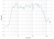
I will take down the high Qes cone tonight so i did a quick FR measurement and took a picture before that. I have my SPL meter at another location so the y axis on FR shows relative level not SPL.
Hi Oliver,
Thank you for your comments, you touched on important matters.
This old saying that turned almost into an axiom that breakup occurs when sound wavelength reaches the diameter of a cone comes from the era of paper cones. Granted like you say you can move the coincidence frequency upwards ( this frequency where the bending wave's speed matches the air speed ) higher than the once matching the cone's diameter. I remember in the first kevlar cones, many had that 3-4 kHz peak.
But there is also the matter of exciting bending waves and as you mention damping plays it role here specially for wave traveling circumferential to voice coil. For radial wave cone termination has a big role.
Also we need to take into consideration that once we hit cone breakup we dont have only bending wave radiation. The effective diameter of the cone just gets smaller with basically a smaller portion of it still acting as piston.
Attachments
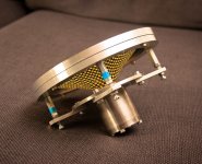
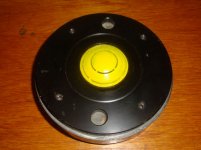
On another note i tested the phase plug in a comp driver with a 44mm Ti diaphragm.
It does have a big dip around 8kHz, i dont have the measured data on this computer but i will show it soon.
This indicates that indeed Ld, the distance between the acoustical boundry and the slit dictates first cutoff frequency. Maintaining a constant volume of air between slit sections doesnt help much after this first test. Im preparing a sheet for constant Ld and will also repeat the measurement with one more constant volume phase plug to make sure.
Attachments
...
I remember in the first kevlar cones, many had that 3-4 kHz peak.
But there is also the matter of exciting bending waves and as you mention damping plays it role here specially for wave traveling circumferential to voice coil. For radial wave cone termination has a big role.
Also we need to take into consideration that once we hit cone breakup we dont have only bending wave radiation. The effective diameter of the cone just gets smaller with basically a smaller portion of it still acting as piston.
Hi Hentai,
such a membrane which reduces the "effective" radius with frequency rising,
needs sufficient inherent damping.
I know it can be done, but you won't usually achieve that e.g. for the radial waves just by proper termination due to the surround.
Since the (wave) impedance of the membrane (for bending waves) changes with frequency, you can IMO optimize the surround just for a small bandwitdh to be "really nonreflective".
Above that range the only chance is sufficient inherent damping.
@ Frank,
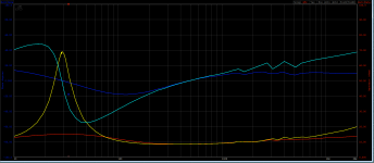
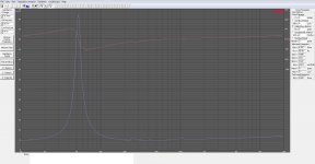
No the suspension has nothing to do with it. I can shift Fs with it but not suppress like this.
This is when i shorten one coil. Btw i don't use a shorten ring that's the next step so the impedance would drop again a bit.
Your plot looks great! Very lineair till 20Khz. Do you use a copper shorten ring?
What are the TS parameters?
cheers,
Last edited:
- Home
- Loudspeakers
- Multi-Way
- Project Ryu - DIY Field Coil Loudspeaker