Yes.... please post a picture of your cone, I would love to see it
man, I need to build that chassis soon

Attachments
Will you make a short description on how you made it
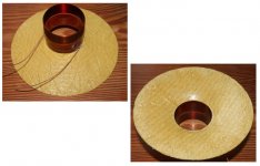
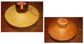
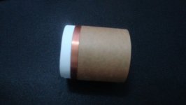
I made this 'mold'
voice coil is put on the centre tap
and diaphragm/cone is molded directly on to it
if needed I can put on more reinforcement on the back
it was supposed to be a midrange only
didnt have ambitions for the heights
Attachments
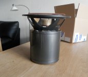
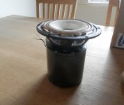
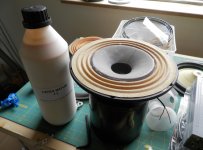
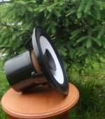
Got the field coils from Hentai today, he did a amassing job. I put on a basket and a cone just to see, it looks wild..Here is some pic's.
Next step is to design a strong basket for the unit.
Take care
Next step is to design a strong basket for the unit.
Take care
Attachments
hey, using a spider for the surround, thats clever
do they have them somewhat smaller ?
btw, I have a DIY cone I made using lighter foaming poly glue
I can post pics if interested
tinitus, you gave me a idea, thanks.....Using a spider could work if it was softer and airtight, I spend some time to figure it out how to losses up the addictive in the spider. I found that ammonia dose the trick, next step is to get it airtight. I found that latex milk dose contains ammonia and can seal the holes in the spider at the same time... and what do you know.... it's works beautifully. Took some pic's.
Attachments
tinitus, you gave me a idea, thanks.....Using a spider could work....
cool
sorry I forgot to answer
I used cheap industrial dust cloth
special papery one with lots of holes
base/resin is ordinary foamy polyurethane glue
made it a long time ago, and would probably do different today
actually, the kind of thin fiber matt you put on walls and ceiling before paiting might work too
but if you want a really light cone, it might be best to use pressure molding, or vacume bag technology
It looks like you have treated some kind of cloth, is that correct and if so what is the base material.
Take care
Hello,
Soon Project Ryu will celebrate 1 year since first post. I'm preparing a new set of tests to celebrate.
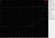
Meanwhile i have tested the double voicecoil theory in which one voicecoil is shorted and one has signal applied to it. The attached image shows the inductance behavior.
Blue line (red for phase) represents inductance of one VC with signal applied and the other in open circuit.
Green line (yellow for phase) represents inductance of one VC with signal applied and the other in short circuit.
As you can see at 1Khz not much of a difference but indeed going up in frequency the shorted VC helps out. Frank was right thinking of this. Ofcourse now the question that remains is this worth getting the extra mass of one more VC or not?
Test was done with identical VC placed in the middle of the gap and copper shorting ring placed under the gap.
As some may noticed i have finally defeated inductance problem. I can now get a good value around 0.5mH at 1khz but i will leave this discussion for later after i arrange all the data.
Soon Project Ryu will celebrate 1 year since first post. I'm preparing a new set of tests to celebrate.
Meanwhile i have tested the double voicecoil theory in which one voicecoil is shorted and one has signal applied to it. The attached image shows the inductance behavior.
Blue line (red for phase) represents inductance of one VC with signal applied and the other in open circuit.
Green line (yellow for phase) represents inductance of one VC with signal applied and the other in short circuit.
As you can see at 1Khz not much of a difference but indeed going up in frequency the shorted VC helps out. Frank was right thinking of this. Ofcourse now the question that remains is this worth getting the extra mass of one more VC or not?
Test was done with identical VC placed in the middle of the gap and copper shorting ring placed under the gap.
As some may noticed i have finally defeated inductance problem. I can now get a good value around 0.5mH at 1khz but i will leave this discussion for later after i arrange all the data.
Attachments
Hi
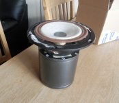
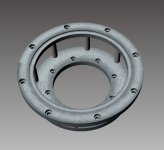
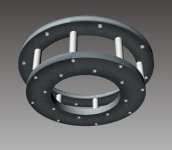
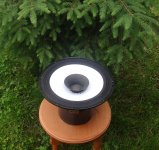
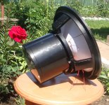
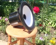
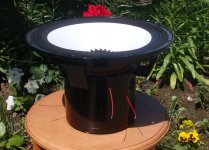
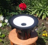
I just got some news, they will start to milling the basket for my unit's Monday. It is made from 10mm aluminium and is black anodized when done, the two rings is hold togeter with 8 psc 10mm spacers.
Here is some pic's
Take care
I just got some news, they will start to milling the basket for my unit's Monday. It is made from 10mm aluminium and is black anodized when done, the two rings is hold togeter with 8 psc 10mm spacers.
Here is some pic's
Take care
Attachments
Hello again,
Been a while since i posted any real data but i've been working in my dungeon here and the next posts will contain some real data.
I have done a few tests involving voice coil design, influence of whizzer and phaseplugs methods of assembly. I'm preparing a motor for a 12 incher but with 38mm voice coil instead of 50mm and in about a couiple of weeks i will show a match between PM and FC, same cone, vc, surrounds etc.
It is very difficult to design a loudspeaker unit, most time you fix a problem and you create another and everytime you find there is room for improvement. However i have finally defeated inductance. I got it below 1mH @ 1kHz, lowest value was 0.4mH and i'm pretty satisfied with it.
I still have a problem im fighting with a resonance around 1Khz, this also made inductance measurements not very accurate, raising the value.
I also tested the double voice coil design with Frank's idea to put one in short circuit. While it does lower inductance with the voice coil blocked (not moving), when the voice coil moves things get weird, you will see.
Today i will post some pictures and from tomorrow if time allows i will start posting about tests and measurements. Would've liked to post it tonight but its late here.
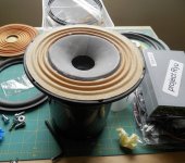
Voice coil now have paper former and i dont believe i will return to anything else anytime soon. There are 3 types:
1. single layer
2. 2 layers - 2 voice coils with posibility to connect series/parallel/independent
3. 4 layers - 2 voice coils like 2 but each voice coils is made of 2 layers in series.
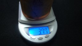
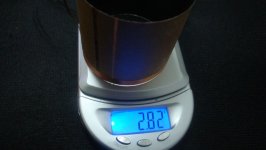
Posibility to connect as 4 ohm, 8 ohm, 16 ohm and voice coil 3 as 32 ohms. Using 0.15mm ECW (copper wire) you can see the weight of each in the pictures.
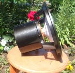
And here is a 12" unit model 0PX (i started with 0AX ) first without whizzer then with whizzer attached. In my back yard for the scenery but im not a good photographer sorry.
Well this is it for tonight. Will get rest and will post more tomorrow and i hope i can attract you in a math discussion at a point.
Hope you like the pictures.
Been a while since i posted any real data but i've been working in my dungeon here and the next posts will contain some real data.
I have done a few tests involving voice coil design, influence of whizzer and phaseplugs methods of assembly. I'm preparing a motor for a 12 incher but with 38mm voice coil instead of 50mm and in about a couiple of weeks i will show a match between PM and FC, same cone, vc, surrounds etc.
It is very difficult to design a loudspeaker unit, most time you fix a problem and you create another and everytime you find there is room for improvement. However i have finally defeated inductance. I got it below 1mH @ 1kHz, lowest value was 0.4mH and i'm pretty satisfied with it.
I still have a problem im fighting with a resonance around 1Khz, this also made inductance measurements not very accurate, raising the value.
I also tested the double voice coil design with Frank's idea to put one in short circuit. While it does lower inductance with the voice coil blocked (not moving), when the voice coil moves things get weird, you will see.
Today i will post some pictures and from tomorrow if time allows i will start posting about tests and measurements. Would've liked to post it tonight but its late here.
Voice coil now have paper former and i dont believe i will return to anything else anytime soon. There are 3 types:
1. single layer
2. 2 layers - 2 voice coils with posibility to connect series/parallel/independent
3. 4 layers - 2 voice coils like 2 but each voice coils is made of 2 layers in series.
Posibility to connect as 4 ohm, 8 ohm, 16 ohm and voice coil 3 as 32 ohms. Using 0.15mm ECW (copper wire) you can see the weight of each in the pictures.
An externally hosted image should be here but it was not working when we last tested it.
An externally hosted image should be here but it was not working when we last tested it.
An externally hosted image should be here but it was not working when we last tested it.
An externally hosted image should be here but it was not working when we last tested it.
And here is a 12" unit model 0PX (i started with 0AX
) first without whizzer then with whizzer attached. In my back yard for the scenery but im not a good photographer sorry.An externally hosted image should be here but it was not working when we last tested it.
An externally hosted image should be here but it was not working when we last tested it.
An externally hosted image should be here but it was not working when we last tested it.
An externally hosted image should be here but it was not working when we last tested it.
An externally hosted image should be here but it was not working when we last tested it.
An externally hosted image should be here but it was not working when we last tested it.
An externally hosted image should be here but it was not working when we last tested it.
Well this is it for tonight. Will get rest and will post more tomorrow and i hope i can attract you in a math discussion at a point.
Hope you like the pictures.
Attachments
-
 DSC03448.jpg68.2 KB · Views: 134
 -
 DSC03447.jpg72.4 KB · Views: 138
 -
 DSC03451.jpg60.1 KB · Views: 140
 -
 DSC03567.jpg696.1 KB · Views: 131
 -
 DSC03564.jpg714.7 KB · Views: 116
 -
 DSC03551.jpg434.5 KB · Views: 127
 -
 DSC03550.jpg447.1 KB · Views: 127
 -
 DSC03549.jpg689.8 KB · Views: 122
 -
 DSC03546.jpg329 KB · Views: 209
 -
 DSC03545.jpg272.1 KB · Views: 209
Hi Hentia
Man that unit looks awesome, very nice job..... I was just about to wright to you, reg. the shorted voice coil see this video... Neodymium magnet in copper pipe - YouTube weird stuff.
Looking forward to see some data.
Keep up to good work, take care
Man that unit looks awesome, very nice job..... I was just about to wright to you, reg. the shorted voice coil see this video... Neodymium magnet in copper pipe - YouTube weird stuff.
Looking forward to see some data.
Keep up to good work, take care
The magnet sets up a current in the copper which creates its own magnetic field. Its repels the magnet.
You need a very strong magnet like neodymium to do this.
I'm going to be starting the same project you guys have been working on. I'm going to be converting some jbl 15" woofers and compression drivers to field coils. They were originally alnico drivers, so I'm using the original magnet structures.
I'm going to try and make my own cones after I wind my coils. But since the woofers will be in bass horns, it will be easier.
But I'm wondering what types of dense paper you had the best luck with. I want a light cone. 30 grams or so would work. But since they will be in a bass horn they need to be stiff. Any advice?
Thanks,
Nick
Hello, yes its the Faraday-Lenz Law.
Nick glad to hear you will come aboard.
Getting the right paper is a trial and error process most of the time. Mostly because most places that sell paper dont provide enough data to compute any real prediction of behavior. Most info you will get will be density which will help you calculate mass.
You can start up with normal calligraphy paper. A friend i know uses Mulberry paper and with good results. I was and still am set with washi, sounds great but hard to work with and usually turns up too heavy to make it stiff.
Curving the cone also makes it stiff.
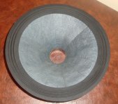
Here is one of my first cones with washi. Pretty stiff, 27g just the cone tho. Even so i liked its sound the most.
What model is the JBL?
Nick glad to hear you will come aboard.
Getting the right paper is a trial and error process most of the time. Mostly because most places that sell paper dont provide enough data to compute any real prediction of behavior. Most info you will get will be density which will help you calculate mass.
You can start up with normal calligraphy paper. A friend i know uses Mulberry paper and with good results. I was and still am set with washi, sounds great but hard to work with and usually turns up too heavy to make it stiff.
Curving the cone also makes it stiff.
Here is one of my first cones with washi. Pretty stiff, 27g just the cone tho. Even so i liked its sound the most.
An externally hosted image should be here but it was not working when we last tested it.
What model is the JBL?
Attachments
Hi Hentai,
Well there 3 late model d130 frames and one k140 frame. They are all the same but just look different. But technically there identical. Same gap width, gap height, and gap flux.
I want to try and make a close copy of a jbl 150-4 with out the taller cone. I was looking at paper last night. I think Ill buy a piece of poster board this weekend and do some experimenting. Probably take me a few try just to get the size right.
Im going to coat the paper with damar varnish I made specifically for this purpose. I will also try pva too. Just to stiffen them.
Thanks,
Nick
- Home
- Loudspeakers
- Multi-Way
- Project Ryu - DIY Field Coil Loudspeaker