In this thread, I'm going to take a stab at describing how the Danley Paraline and the Sausalito Audio Works lens work.
I'm not 100% certain that I'm correct - but it should be fun to explore it.
First, some pics:
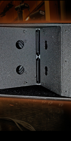
VTC Paraline at the throat of a synergy horn (It's the long skinny lens in the center)
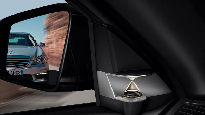
Sausalito Audio Works lens in a Bang & Olufse Beolab 5
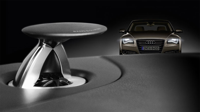
SAW lens in an Audi A8
If anyone curious how these work, they basically take the wavefront off of the driver at the base, and then they reflect it 90 degrees.
IMHO, the primary advantage of the SAW lens and the Paraline is that it allows you to get very very very narrow directivity, without using a looooooooooong waveguide or horn.
For instance, according to the docs, one of the Paralines has the directivity of a horn that's over a meter deep - but the Paraline is about 1" deep!
Stay tuned to see how the magic happens...
I'm not 100% certain that I'm correct - but it should be fun to explore it.
First, some pics:
VTC Paraline at the throat of a synergy horn (It's the long skinny lens in the center)
An externally hosted image should be here but it was not working when we last tested it.
Sausalito Audio Works lens in a Bang & Olufse Beolab 5
SAW lens in an Audi A8
If anyone curious how these work, they basically take the wavefront off of the driver at the base, and then they reflect it 90 degrees.
IMHO, the primary advantage of the SAW lens and the Paraline is that it allows you to get very very very narrow directivity, without using a looooooooooong waveguide or horn.
For instance, according to the docs, one of the Paralines has the directivity of a horn that's over a meter deep - but the Paraline is about 1" deep!
Stay tuned to see how the magic happens...
The only basic premise you need to understand about the Paraline is if the dimensions of the acoustic pathway are kept to 1/2 a wavelength or less of the highest frequency of interest, then it will pass through the lens largely unaffected. As long as the wavelength of the highest frequency is significantly larger then its passage way, it will move through the lens like water through a pipe. Exactly like long and low frequency waves in folded bass horns can't acoustically "see" the flat corner bends. It’s simply just a matter of scaling the model to fit the frequency. Sound doesn’t care what frequency it is, it behaves the same way.
The only basic premise you need to understand about the Paraline is if the dimensions of the acoustic pathway are kept to 1/2 a wavelength or less of the highest frequency of interest, then it will pass through the lens largely unaffected. As long as the wavelength of the highest frequency is significantly larger then its passage way, it will move through the lens like water through a pipe. Exactly like long and low frequency waves in folded bass horns can't acoustically "see" the flat corner bends. It’s simply just a matter of scaling the model to fit the frequency. Sound doesn’t care what frequency it is, it behaves the same way.
True, but the information on making a proper reflector is interesting.
There have been a half dozen omnipolar projects on diyaudio which could have been improved with the information from this patent, so thought it would be worthwhile to walk through it.
(BTW, nearly everything you need to know to make one is in the patent, it's wonderfully detailed.)
As noted in the first post, the 'neat' thing about these inventions is that they give you directivity control that's similar to a long deep horn, but without the brutal space requirements. For instance, one of the Paraline devices has a depth of about an inch, and claims to have the directivity of a horn which is over a meter long. (According to the marketing literature.)
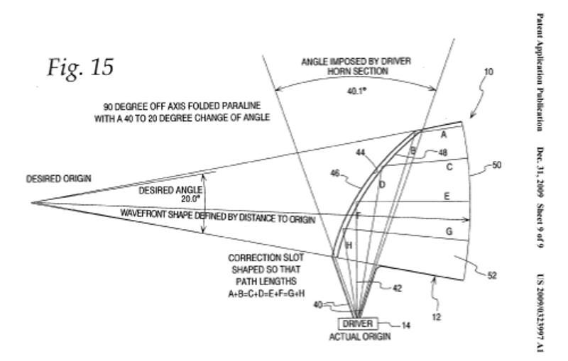
The way that this is achieved is by using a clever reflector. Basically the driver faces upward, and the sound is reflected ninety degrees. The pic above, from the paraline patent, illustrates how this works.
If I'm not mistaken, the same math can be used to build your own S.A.W. lens.
I took a stab at modeling one of these in Xara, using the dimensions from the patent.
If you'd like to make your own, here's how you could replicate this:
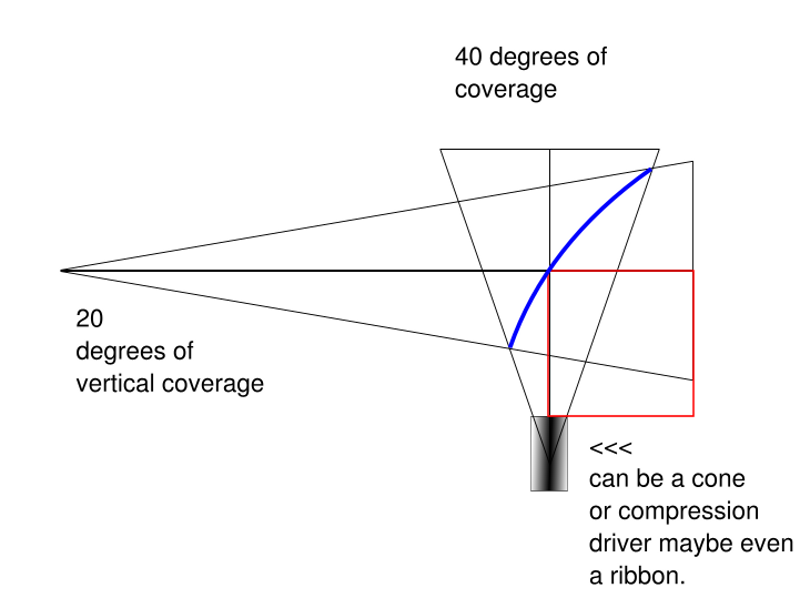
- First, figure out what vertical coverage you want. The vertical coverage will determine if the driver has a strong forward lobe, or a pattern that's closer to a conventional driver. There are a couple of advantages to using a narrow pattern. First, it raises the on-axis SPL by focusing the energy into a narrower angle. Very much like a horn. Second, and more important, it improves the vertical directivity. (You can see this in the measurements of the B&O speakers.) The vertical directivity is improved because a speaker on a flat baffle will begin to 'beam' as frequency rises. The reflector in this lens assembly equalizes the pathlength, and that improves vertical directivity.
In my pic above, I used the exact same vertical coverage as the patent - twenty degrees. - Second, figure out the angle of the triangle that passes through your driver. It's not clear to me what this signifies - perhaps something to do with the direcitivity of the driver at the apex? I simply used what's in the patent - forty degrees. If I had to hazard a guess, I would think that compression drivers would have a narrower angle than conventional radiators, and ribbons would have the widest angle of all. This is because a compression driver has very narrow directivity at the driver exit, conventional drivers are wider, and ribbons are widest of all.
Again, just a guess. I used 40 degrees. - Third, you need to figure out where the two triangles intersect. From looking at the patent, there is a right triangle that's formed where the center of the driver's diaphragm reflects at 90 degrees off of the reflector.
You can see it in my pic as a red square in the bottom right. The edges of that square are equal.
In order for everything to work, the pathlengths have to be equalized quite accurately. If not, you'll get comb filtering and limited bandwidth.
So if you're going to try and build one of these, I'd measure those two distances quite carefully. If there's a tweeter at the apex, I'll bet that an error on the order of a fraction of an inch would make a measurable difference in the response.
- Fourth, you need to figure out the height of the triangle that determines the vertical coverage of the device.
In the pic above, I used a height of 15cm. This height was dictated by the project that I am working on - I am going to build a synergy horn similar to the VTC paraline.
For your project, the height of the device would largely depend on your crossover point.
If there is a formula to determine the height of the triangle, I am not aware of what it is.
Here are some guesses, which might be helpful for you:
An externally hosted image should be here but it was not working when we last tested it.
#1 - in the SAW waveguide, the height of the triangle seems to be dictated by the crossover point. For instance, in a horn, the directivity is constrained when the wavelength is equal to or smaller than the diameter of the horn or waveguide. IE, if a horn or waveguide has a mouth that's 8cm in diameter, it will constrain directivity down to 4,250 hz. Looking at the Beolab 5, we see something similar; the directivity is constrained by the aluminum discs above and below the driver.
The dimensions of the paraline are simpler to calculate; it's plain ol' horn math and I'll get to that in a future post.
Your drawings look a lot like the microwave horns that have been around for a while. Was this considered a new invention for Sausilito?
I also looks like there are two areas with very different path lengths. The back half of the tweeter dome sees the convex surface, as you have drawn in your cross section. The front half sees the upper concave reflector that appears to be a longer path length. As with all of these reflectors, there is also interference with the direct path from the tweeter. This path is shorter so there usually is significant vertical nulling from those 2 (or 3) paths.
David S.
Attachments
The length of the initial horn throat prior to the Paraline curve portion of the horn is also crossover frequency dependent. Too short, and the initial horn portion will not have pattern control, which will result in diffraction in the Paraline transition, resulting in multiple reflections off the latter horn section sidewalls , resulting in severe frequency dependent comb filtering.It's not clear to me what this signifies - perhaps something to do with the direcitivity of the driver at the apex?
In the pic above, I used a height of 15cm. This height was dictated by the project that I am working on - I am going to build a synergy horn similar to the VTC paraline.
For your project, the height of the device would largely depend on your crossover point.
If there is a formula to determine the height of the triangle, I am not aware of what it is.
In the SAW waveguide, the height of the triangle seems to be dictated by the crossover point. For instance, in a horn, the directivity is constrained when the wavelength is equal to or smaller than the diameter of the horn or waveguide. IE, if a horn or waveguide has a mouth that's 8cm in diameter, it will constrain directivity down to 4,250 hz. Looking at the Beolab 5, we see something similar; the directivity is constrained by the aluminum discs above and below the driver.
The diagram below shows the high frequency green lines as “good”, and the lower frequency orange and red lines as “bad”.
For the design to work properly, the initial horn exit diameter must be at least a wavelength of the low frequency crossover desired, about six inches or more for a 2000 Hz crossover.
The design is good, but as in all horn designs, size does matter, shrink this concept from a 45 inch wide horn exit (as in the DSL JH-90) down to a 22.5” horn exit and the crossover point must be raised an octave to keep pattern control and avoid peaks and dips.
Art
Attachments
The length of the initial horn throat prior to the Paraline curve portion of the horn is also crossover frequency dependent. Too short, and the initial horn portion will not have pattern control, which will result in diffraction in the Paraline transition, resulting in multiple reflections off the latter horn section sidewalls , resulting in severe frequency dependent comb filtering.
The diagram below shows the high frequency green lines as “good”, and the lower frequency orange and red lines as “bad”.
<snip>
Art
Art,
Thanks for taking the time to type this up. I've studied this for a few hours and it's really helped me understand what's going on in the paraline.
As noted above, I spent a few hours studying the paraline patent, and there are some interesting innovations in here which aren't obvious.
First, the paraline appears to be a way to reduce the depth of a narrow angle horn. For instance, if you make a horn with a coverage angle of 20 degrees, it is going to be VERY deep. This is basic geometry; with a narrow coverage angle it will have a small mouth but a very long depth. Similar to a length of pipe, but slowly expanding.
But there are a couple of things happening in the Paraline which aren't immediately obvious.
The first is that it's delaying part of the wavefront.

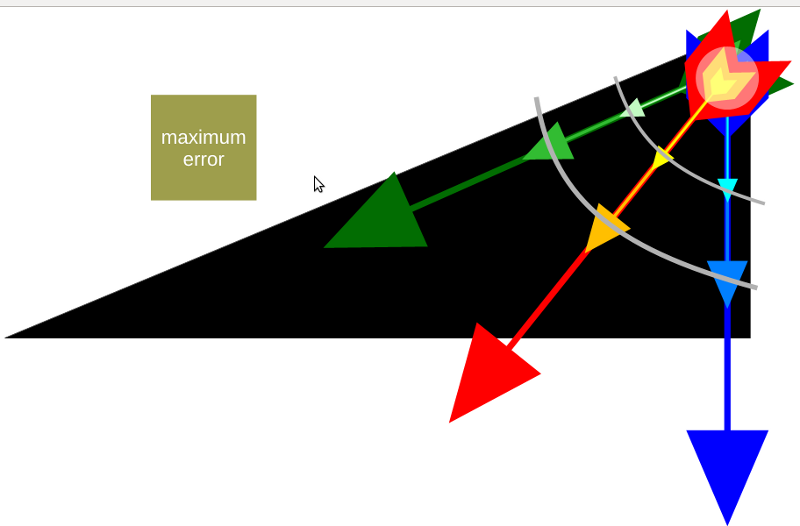
I think this is easiest to understand if you look at the wavefront of a horn with a wide coverage angle. Car audio horns are a good example of this. They have a wavefront that's about 45 degrees horizontally, but less than half that vertically. Due to the horizontal angle, the edges of the wavefront lag the apex of the wavefront.
That probably doesn't sound like a big deal; but it makes it very difficult to get the midrange in-phase with the tweeter at the crossover point in more than one location.
In the pic above, I've done my best to illustrate the problem. See how the wavefront at the edge of the horn is a few miiliseconds BEHIND the wave at the center if you're off axis? The green box, labeled 'maximum error', is there to show how much delay is acceptable before the phase gets screwed up. It signifies one quarter wavelength at a crossover frequency of 2000hz. (4.25cm)
In other words, you'll have excellent frequency response, phase response and imaging, but only if you're on axis.
As I see it, there are a three solutions to the problem. The first is to listen to both speakers on-axis. The second is to delay the part of the wavefront that's at the edge of the horn. Which is exactly what the Paraline does. The last is to use a very narrow coverage angle, so that the difference in delay between the edges of the horn and the center of the horn is minimized. Which might explain why the Synergy horns use a narrower angle than the Unity horns.
For instance, let's say you're using one of these devices, with a mouth that's 30cm across. And you're crossing over to a midrange with a diaphragm that's 20cm across. The directivity of the midrange and the horn are dramatically different at the crossover point. And this means that you can get the response in-phase at one angle, but not at *all* angles.
In other words, if you optimize the phase-response on-axis, it will suffer off-axis, because the wavefront of the horn is dramatically different than the wavefront of the midrange.
The Paraline's most interesting feature, IMHO, is that it can 'bend' the wavefront. There's a time delay imposed by the path through the Paraline, but that time delay varies by a few centimeters. Basically the wave at the center of the horn is 'pulled back' by the Paraline.
This time delay creates some very interesting advantages, particularly when you're using lots of drivers.
First, the paraline appears to be a way to reduce the depth of a narrow angle horn. For instance, if you make a horn with a coverage angle of 20 degrees, it is going to be VERY deep. This is basic geometry; with a narrow coverage angle it will have a small mouth but a very long depth. Similar to a length of pipe, but slowly expanding.
But there are a couple of things happening in the Paraline which aren't immediately obvious.
The first is that it's delaying part of the wavefront.
I think this is easiest to understand if you look at the wavefront of a horn with a wide coverage angle. Car audio horns are a good example of this. They have a wavefront that's about 45 degrees horizontally, but less than half that vertically. Due to the horizontal angle, the edges of the wavefront lag the apex of the wavefront.
That probably doesn't sound like a big deal; but it makes it very difficult to get the midrange in-phase with the tweeter at the crossover point in more than one location.
In the pic above, I've done my best to illustrate the problem. See how the wavefront at the edge of the horn is a few miiliseconds BEHIND the wave at the center if you're off axis? The green box, labeled 'maximum error', is there to show how much delay is acceptable before the phase gets screwed up. It signifies one quarter wavelength at a crossover frequency of 2000hz. (4.25cm)
In other words, you'll have excellent frequency response, phase response and imaging, but only if you're on axis.
As I see it, there are a three solutions to the problem. The first is to listen to both speakers on-axis. The second is to delay the part of the wavefront that's at the edge of the horn. Which is exactly what the Paraline does. The last is to use a very narrow coverage angle, so that the difference in delay between the edges of the horn and the center of the horn is minimized. Which might explain why the Synergy horns use a narrower angle than the Unity horns.
For instance, let's say you're using one of these devices, with a mouth that's 30cm across. And you're crossing over to a midrange with a diaphragm that's 20cm across. The directivity of the midrange and the horn are dramatically different at the crossover point. And this means that you can get the response in-phase at one angle, but not at *all* angles.
In other words, if you optimize the phase-response on-axis, it will suffer off-axis, because the wavefront of the horn is dramatically different than the wavefront of the midrange.
The Paraline's most interesting feature, IMHO, is that it can 'bend' the wavefront. There's a time delay imposed by the path through the Paraline, but that time delay varies by a few centimeters. Basically the wave at the center of the horn is 'pulled back' by the Paraline.
This time delay creates some very interesting advantages, particularly when you're using lots of drivers.
Last edited:
Hi Patrick (john), all
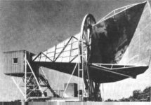
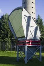
Speaker Dave has posted a couple pictures of the microwave horn / reflector that inspired the Paraline.
That microwave horn / reflector worked vary well and was the backbone of our cross country telephone system for a long time and lead to the discovery of our cosmic background radiation.
The problem when applied to acoustics is that unlike microwave, one is dealing with a variable wavelength signal and “how a reflector works” is partly dependant on how large it is. In the reflection based system, one has to have a reflector many many wavelengths across before it starts to be something like what we think of as a mirror (the same at different frequencies).
Being sort of a horn guy I guess, I wanted to find a solution that was compatible with horn loading as well so that kind of steered my direction.
The Paraline only uses the path length and natural point source radiation of the driver pressure and is free from the variable reflector issue.
If you picture that from the blue line forward forming the vertical plane is one thin slot and the upward horn ends at the blue line, the blue line is a slot that connects the two layers.
Sound acts like a simple pressure, like a fluid, flowing around a corner if the dimensions are small relative to the wavelength while it can act like light if the dimensions are very large. This depends on the dimensions being small for the sound to bend, it’s own pressure makes it go the right place.
The shape of the Paraline slot defines where the radius of curvature or equivalent origin is for the exit wave front relative to the incoming wave front.
In the Paraline most in use, the configuration is a radial sweep of the first idea.
The VTC graphic is nice and shows the guts of the one they use.
The driver connects through the opening and the sound bends to radiate away radially 360 degrees but within a thin airspace.
The thickness dimension is too small to allow a reflected signal, in order to bend around the two 90 degree corners, the dimensions have to be no more than around 1/3 wl at the highest frequency. Radiating away from the driver, it has a 360 degree expansion.
After wrapping around the slot, the timing / pressure produces the desired exit waterfront which converges at the center, bends 90 degrees again and enters the rear of the horn. This imparts the same curvature one would have if the horn were made conventionally but was very very deep physically.
The ones we use are very similar to the VTC units and your right one advantage is they can be placed end to end easily. The GH-60’s at Lambau field use them .
One other less obvious thing is that as the sound radiates away from the driver, the spl is falling according to area. This means with a constant thickness, the top and bottom are automatically -3dB relative to the center. The wider the vertical pattern angle, the greater the amplitude shading the center relative to the ends. Anyway since when the dimension is small one can think in power per area, the spl in that plane can be tailored to a degree.
The “J” cabinets use something kinda like a paraline that I called a layered combiner.
You can’t add high frequency drivers together without making an interference pattern up high, Y throats don’t work and a well known 4 driver combiner is only about 4 dB more powerful than a single of the drivers on a normal horn.
That single driver limit had always been the loudness limit on the Synergy horns but the J horns with the combiner I could get around that by producing the radiation of a single source.
As soon as the patent orifice has it available to the public it can explain it.
This was I think the hardest nut I ever had to crack, it took 4 months to get a workable design in the JH-90 (J1) but the latest one has 64 hf drivers that add into one wave front (obviously had to have a working name of the mosquito beater haha). At one point I was getting bummed out and afraid I had been wrong when I said ‘I think I see a way to do it” but ultimately, the solution was very much like the fleeting idea months before.
A couple J cabinet video demo’s using the combiner;
Adjust the volume to scale to live at about 1:30 when the operator walks up to the guy next to the camera guy and talks. It was pretty loud then but later a bunch of people (stadium sound people) took off in cars to hear from farther away (with these the sound changes very little with distance compared to normal speakers), the cops came and they were not happy. Anyway, except for his mic being squashed by the subwoofer, I thought his video captured being there pretty well.
Danley Sound Labs - YouTube
This was a larger space using three J cabinets facing right, left and center, they are the little dark blob under the scoreboard. Keep in mind a stadium is a pretty live place with no people.
Penn State Demo.MOV - YouTube
Best,
Tom Danley
Danley Sound Labs

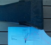
Here's a drawing of an underdash horn, using the same reflector assembly that's in the paraline and in the SAW lens.
Here's an explanation of what's going on in the picture:
- The red triangle defines the forward angle, and is 20 degrees, just like the paraline patent
- The yellow triangle is the 'initial' wavefront, off of the compression driver
- The blue rectangle is the footprint of the horn. Basically it's there to define how much space we have for the horn. In this case, it's 5" by 15"
- The dark blue line is probably the most important curve in the whole horn. This is the reflector, which is designed to bend the wavefront. One thing which isn't obvious, but is very important, is that the wavefront is flat. This is a big deal in car audio, because it 'drags' the image towards the center. This might not be obvious, but flattening the wavefront drags the image towards the center because it creates a time delay. (it basically delays the center of the wavefront, and since the horns are cross-fired in a car, it 'drags' the speaker backwards. Basically drags the image towards the left.
- The black circles are simply there to reduce diffraction. Each circle reduces diffraction at the mouth of the horn.
Tom,The “J” cabinets use something kinda like a paraline that I called a layered combiner.
This was I think the hardest nut I ever had to crack, it took 4 months to get a workable design in the JH-90 (J1) but the latest one has 64 hf drivers that add into one wave front (obviously had to have a working name of the mosquito beater haha).
64 HF drivers should help keep up with the 18 dB air loss of 10kHz at 400 feet, a “mosquito beater” indeed!
Would you share a peek under the hood showing the arrangement of the drivers?
Art
Did I read 64 HF drivers? OMG!.... Tom, your're sure one hell of a crazy guy

I wonder how low you could cross that over. 64 compression drivers have more surface area than a pair of 12 woofers!
Obviously you couldn't get away with a 80hz crossover on a compression driver, even if you use an array of them, but that much surface area could definitely allow a lot of flexibility on the crossover point of a synergy horn.
Hi Guys
I got into audio by being a DIY’r so there aren’t a lot of things I enjoy more than explaining a new invention or lurking as others go through the process figuring them out like you guys.
I wish I were able to be of more help at times too, Art, I wish I could explain how the combiner works but at the moment I can’t.
If you are going to infocom, I can show you there.
We are running a race where the largest companies strongest legs are image marketing creates and it’s budget and our only strong leg is what people hear in a side by side demo.
What seems to be happening is when you make something that nothing else does, people find uses for it. The Jericho cabinet came to be when a sound guy we know said he bet if you could do a live show up to a couple thousand with one box per side that sounded like an SH-50, that would sell.
Well the concert sound industry largely “knows” all about line arrays, rigging, nice color mapping programs, the things needed to get concert sound. In the stadiums, it is the same concert sound stuff that is being bumped out because it sounds dreadful in a side by comparison.
The market where the acoustic problem is the hardest and a solution most appreciated (by people who couldn’t care less about a name or approach they never heard of) is commercial sound especially now in stadiums and that is where the focus is.
The 64 hf driver device is for very long distances where the hf air absorption can be severe. The first time I heard a stadium install playing CD’s with the Jericho’s and 812’s (BYU) I walked the stadium and then sat facing the system from the far side (about 750 feet).
The two things I thought were wow, they could play movies like U-571 through this and if I had a bit more twinkle, it would sound like the speakers were 20 feet away. In hot humid weather, the hf absorption is greater. The cool thing about a CD point sources is except for the hf absorption, the spectral balance doesn’t change with distance while interference pattern arrays have a pronounced maximum usable throw and constantly variable frequency response that requires fancy colorful displays to hide that feature set..
This box should satisfy the very large scale sound requirements for "giant fi".
Here is a video of the J2 being used on it’s maiden public test last fall.
This is more powerful than the J1 and J3 I have posted previously and this Synergy horn has 42 drivers, 12 are hf compression drivers.
In this case, with a live band, to me it sounded like too much high end in this use, given how far away it was.
Also, normally, these would be flown and aimed “at the back row” so the underside of the pattern tapers the spl.
If you get the pattern bottom’s shape and flying height dialed in, the spl only varies a small amount from the closest to farthest seats.
Best,
Tom
Danley Jericho PA speaker, J2 at 300 Yards - YouTube
Tom,Hi Guys
I got into audio by being a DIY’r so there aren’t a lot of things I enjoy more than explaining a new invention or lurking as others go through the process figuring them out like you guys.
I wish I were able to be of more help at times too, Art, I wish I could explain how the combiner works but at the moment I can’t.
If you are going to infocom, I can show you there.
The 64 hf driver device is for very long distances where the hf air absorption can be severe. The first time I heard a stadium install playing CD’s with the Jericho’s and 812’s (BYU) I walked the stadium and then sat facing the system from the far side (about 750 feet).
The two things I thought were wow, they could play movies like U-571 through this and if I had a bit more twinkle, it would sound like the speakers were 20 feet away. In hot humid weather, the hf absorption is greater.
Here is a video of the J2 being used on it’s maiden public test last fall.
This is more powerful than the J1 and J3 I have posted previously and this Synergy horn has 42 drivers, 12 are hf compression drivers.
Best,
Tom
I couldn’t hear a whisper (or twinkle ;^) of cymbals (8K +) in the J2 video, but plenty of high mids, the steel drum sound was certainly ringy!
12 HF drivers per cabinet seems a bit light on the VHF for 900 feet.
Upping that to 64 HF drivers you finally got around to fixing the problem I brought up (and Ivan Beaver acknowledged) 10/7/10, and now you won’t show me how ;^) ?
Wish I could make it to infocom, but have another trip north east around the same time.
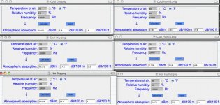
This guy has the best collection of audio calculators:
Calculation method of absorption of sound by the atmosphere air damping dissipation absorbtion - Attenuation of sound during propagation outdoors outdoor - sengpielaudio Sengpiel Berlin
Hot and humid environments have less HF atmospheric absorption than dry, the opposite is true when the environment is cold. Somewhere in the middle temperature range both are pretty bad.
In the high desert of New Mexico outdoor concert season we see temperatures in the 90’s and relative humidity in the 20s, we need two to four times the HF horsepower from my native Minnesota, which could be 90 degrees with 80+ relative humidity.
With summer temperature often ranging as much as 50 degrees during day to night here, some drastic EQ changes sometimes need to be made, the crisp clear sound in the early morning quickly turns to mud once the sun shines.
Then the thermal gradients start to happen, even with a single point source they can point the sound in a different direction than the cabinets..
Perhaps you should make temperature/humidity/thermal gradient angle adjustment actuators optional on your stadium installs :^).
I don’t miss the Minnesota humidity, but I miss the HF, have the double whammy of age and absorption going on here :^(.
Art
Attachments
Last edited:
The world would be a much simpler place is we could do acoustics by simply drawing straight lines. Problem is that sound is waves not light rays and they don't work like light rays. They go arround corners and diffract at edges, all kinds of things that "rays" do not account for. So I simply discount any argument that uses "rays" to explain what happens. Like the "acoustic lens" thing that was shown earlier. Measurements of a real device show that it doesn't act much like it is supposed to except over a very narrow range of frequencies. But thats OK, it looks cool and marketing likes that - so it doesn't actually have to work. The real disappointing thing is that the techniques that actually do work aren't all that "cool" looking and tend to be much larger than we would like. So its just easier to do it wrong and looking good.
- Status
- This old topic is closed. If you want to reopen this topic, contact a moderator using the "Report Post" button.
- Home
- Loudspeakers
- Multi-Way
- ~ Sunshine ~