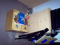
Warm greetings, gurus of DIYAudio! Would like your advice on what to do with these (47X25X30 cm) Monitor Audio R300 oldies but goodies, which I picked up second-hand for £60. ")
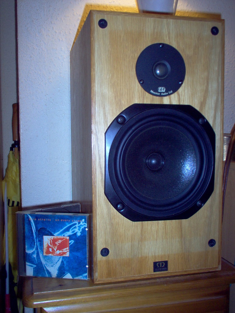
Currently working OK, but I've had to strip out the dried-up ferrofluid gunge from the tweeters with a blotter to get any top-end, and they sound a bit harsh and sibilant at the top, and a bit lumpy in the Infinite Baffle bass for my bluegrass style tastes.
The front end, Rotel RA-931 25WPC Amp, RT-950BXTuner and RCD-965BX LE CD player:
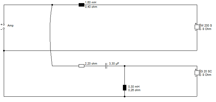
The speakers have a simple inductor on the bass, and a 2nd. order RCL filter on the metal domes, with 2.2 ohms series resistor and 3.3 microfarad capacitor plus coil, @ 90dB efficiency:
I could just slot in a 8" Fostex FF225WK fullrange unit and a 65mmX190mm bass reflex tube in the tweeter hole and there is little carpentry involved according to my measurements with a cabinet volume around 28L, or just replace the 94mm tweeter with a Morel Classic CAT308-94. I COULD fit a reflex port on the back if I stick with existing bass unit, but know nothing about what would be a suitable size or whether it is feasable. Because I like bass reflex, and the way it sounds more alive. Or perhaps I should just replace the tweeter ferrofluid and get it sounding smoother?
Any thoughts or advice? It would be much appreciated.
Currently working OK, but I've had to strip out the dried-up ferrofluid gunge from the tweeters with a blotter to get any top-end, and they sound a bit harsh and sibilant at the top, and a bit lumpy in the Infinite Baffle bass for my bluegrass style tastes.
The front end, Rotel RA-931 25WPC Amp, RT-950BXTuner and RCD-965BX LE CD player:
The speakers have a simple inductor on the bass, and a 2nd. order RCL filter on the metal domes, with 2.2 ohms series resistor and 3.3 microfarad capacitor plus coil, @ 90dB efficiency:
I could just slot in a 8" Fostex FF225WK fullrange unit and a 65mmX190mm bass reflex tube in the tweeter hole and there is little carpentry involved according to my measurements with a cabinet volume around 28L, or just replace the 94mm tweeter with a Morel Classic CAT308-94. I COULD fit a reflex port on the back if I stick with existing bass unit, but know nothing about what would be a suitable size or whether it is feasable. Because I like bass reflex, and the way it sounds more alive. Or perhaps I should just replace the tweeter ferrofluid and get it sounding smoother?
Any thoughts or advice? It would be much appreciated.
Last edited:
I'm just adding this useful info for anyone brought here by google.
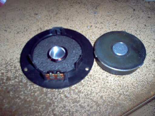
The 94mm metal dome tweeters turn out to be SEAS Prestige H0414-08 19TAF/G , and available here in UK.
SEAS info: H0414-08 19TAF/G
There is a similar fabric dome alternative too, SEAS H0737-08 19TFF 1, which I think was fitted to earlier Monitor Audio R300 models: H0737-08 19TFF 1
As it goes, I've got them working nicely now, because the Rotel RA-931 amp speaker fuses turned out to be suffering from corrosion, which I've cleaned off. I'm just missing the ferrofluid.
Turns out they're called Monitor Audio R300/MD speakers. MD for metal dome tweeter, no doubt.
Yes, you're right, placement matters with these babies. Getting them off the ground makes a big difference to the bass, which is then actually quite deep and uncoloured.
I've learned huge amounts hanging round here, and think I can do something about the MD tweeters:
The tweeters have a 2.2 ohm series resistor, but not the parallel arm of the attenuator. I'm going to try a BBC monitor-style Zobel RC network in parallel with the tweeters, as explained in the Arpeggio Loudspeaker article to flatten the impedance curve to 6 ohms. Failing that, I'll replace the tweeters with the fabric domes, which have a more extended HF and will restore the missing ferrofluid.
Seems like a plan?
Yes, you're right, placement matters with these babies. Getting them off the ground makes a big difference to the bass, which is then actually quite deep and uncoloured.
I've learned huge amounts hanging round here, and think I can do something about the MD tweeters:
An externally hosted image should be here but it was not working when we last tested it.
The tweeters have a 2.2 ohm series resistor, but not the parallel arm of the attenuator. I'm going to try a BBC monitor-style Zobel RC network in parallel with the tweeters, as explained in the Arpeggio Loudspeaker article to flatten the impedance curve to 6 ohms. Failing that, I'll replace the tweeters with the fabric domes, which have a more extended HF and will restore the missing ferrofluid.
Seems like a plan?
Fixing the impedance this way makes a speaker an easy load for an amplifier. Morgan has done this especially with a full range driver that is intended for use with valve amplifiers.
The problem in your case is that you have a crossover between the amp and the speaker. This crossover is probably having some degree of influence in the region to be affected by your RC circuit.
Generally speaking, this means that attempts to 'fix' the impedance at the speaker will not guarantee that it looks this way to the amp. Secondly and more importantly it will change the nature of the impedance for which the crossover was designed.
Specifically it may cause a little top end rolloff. If it happened to be the amount you were hoping for it would be pure coincidence, but there's no harm in trying.
Another possibility would be to put a resistor in parallel with the tweeter to add the second leg of an L-pad, as you were saying. This would have the dual effect of easing the top end as well as applying some damping to the tweeters resonance from the point of view of the existing crossover.
I was thinking of a R=8 ohm Zobel that kicks in around 5kHz, which I'd hope is sufficiently above the crossover point. I've yet to work out exactly what the crossover is doing beyond being second-order. But I take your point that a straight resistor is going to be much easier and do much the same thing really.
It might be a resonance on the metal tweeter in the end. They always tended to be a bit harsh. I think I've got hours of fun here trying stuff. Thanks, AllenB.
I'll update with the findings.
It might be a resonance on the metal tweeter in the end. They always tended to be a bit harsh. I think I've got hours of fun here trying stuff. Thanks, AllenB.
I'll update with the findings.
You will have your work cut out for you Just to clarify it was the lack of ferrofluid I was thinking about. The resistance could make changes there as well as what the RC would do...and if you were thinking of trialling an RC, don't limit it to just the Zobel values, other values of R and C might help. Good luck.
Just to clarify it was the lack of ferrofluid I was thinking about. The resistance could make changes there as well as what the RC would do...and if you were thinking of trialling an RC, don't limit it to just the Zobel values, other values of R and C might help. Good luck.My understanding is that the removal of the ferrofluid would effect the impedance rise and position of Fs as much or more than the impedance rise from coil inductance. The x-over will be effected by the impedance changes around Fs of the tweeter, not so much by the rising impedance from inductance far above the x-over point. A Zobel network is not normally used to correct the impedance rise at tweeter Fs (unless I am missing something?), what you need IMO, is a series notch filter, and/or a re-evaluation of x-over component values. I would not be surprised if the "harshness" you describe is caused by a combination of sensitivity rises around tweeter Fs (due to new higher impedance) and the 8" drivers beams and peaks
I want that ferrofluid back! I've always liked fabric domes over metal ones. Bit mushy, but they don't have that horrible ringing. Look at that SEAS Metal dome again:
Horrible things happening at high frequency. Goes up and down like crazy.
Seems this Zobel correction is a doddle. There's a calculator at DIY Audio Projects:
Speaker Zobel / Impedance Equalization Network Circuit Calculator
Putting in 6.2R and 0.05mh for the SEAS Fabric H0737-08 19TFF 1 , gives 7.75R and 0.832uF. How easy is that.
Reckon 1uf audio grade polypropylene capacitors and 8 ohms wirewound resistors can't be far wrong. I'll order the fabric dome tweeter replacements and have a go at this.
An externally hosted image should be here but it was not working when we last tested it.
Horrible things happening at high frequency. Goes up and down like crazy.
Seems this Zobel correction is a doddle. There's a calculator at DIY Audio Projects:
Speaker Zobel / Impedance Equalization Network Circuit Calculator
Putting in 6.2R and 0.05mh for the SEAS Fabric H0737-08 19TFF 1 , gives 7.75R and 0.832uF. How easy is that.
Reckon 1uf audio grade polypropylene capacitors and 8 ohms wirewound resistors can't be far wrong. I'll order the fabric dome tweeter replacements and have a go at this.
Apologies if this is turning into a BLOG, but good progress on these speakers.
Had them apart, and decided to go with the 8R2 7W Wirewound/680nf Capacitor Zobel:
This leaves the crossover looking like this according to my multimeter, with LP 1.56mh, HP 2R2, 3.3uF, 0.27mH plus the added Zobel Network which is 8R2/680nF:
Quite easy to do since the capacitor fitted exactly in the HP coil:
The metal tweeters are a bit ropey, IMO. 1700Hz Fs is kinda stoneage, but it's sounding extremely good now! The top end has improved DRAMATICALLY with the Zobel. Very smooth and laid-back, a taste of the high-end.
Had them apart, and decided to go with the 8R2 7W Wirewound/680nf Capacitor Zobel:
An externally hosted image should be here but it was not working when we last tested it.
This leaves the crossover looking like this according to my multimeter, with LP 1.56mh, HP 2R2, 3.3uF, 0.27mH plus the added Zobel Network which is 8R2/680nF:
An externally hosted image should be here but it was not working when we last tested it.
Quite easy to do since the capacitor fitted exactly in the HP coil:
An externally hosted image should be here but it was not working when we last tested it.
The metal tweeters are a bit ropey, IMO. 1700Hz Fs is kinda stoneage, but it's sounding extremely good now! The top end has improved DRAMATICALLY with the Zobel. Very smooth and laid-back, a taste of the high-end.
It's good to hear you are making this kind of progress.
Just to add some spice I'd like to mention Head Related Transfer Function (HRTF). It's controversial and I'm just throwing it out for what it's worth, but attempts to correct for it seem to add a good quality to some peoples speakers.
Another suggestion, although the results are likely to be subtle at best, is to trial removing the capacitor from within the inductor. Since capacitors have a little inductence themselves due to their being wound, there is the possibility of interaction.
Just like to add that I once used Vifa aluminium domes (some time ago), and they clearly sounded like a piece of foil. Apart from that, they had very good qualities and I liked them.
It's good to hear you are making this kind of progress.
Just to add some spice I'd like to mention Head Related Transfer Function (HRTF). It's controversial and I'm just throwing it out for what it's worth, but attempts to correct for it seem to add a good quality to some peoples speakers.
Another suggestion, although the results are likely to be subtle at best, is to trial removing the capacitor from within the inductor. Since capacitors have a little inductence themselves due to their being wound, there is the possibility of interaction.
Just like to add that I once used Vifa aluminium domes (some time ago), and they clearly sounded like a piece of foil. Apart from that, they had very good qualities and I liked them.
Flippin' eck, AllenB, you kept me awake worrying about that capacitor within the coil...
Fixed it now. Maybe sounds better too. Dunno really.
An externally hosted image should be here but it was not working when we last tested it.
Don't think Monitor Audio have done much better in some respects...
Currently investigating relative polarity of tweeter and bass. The white (tweeter) and red (bass) wires from the crossover turn out to be hot or positive. The speakers are marked with positive terminals, which mark the forward direction of movement for a 1.5V battery when +ve end connected to hot terminals of the speakers.
Original Filter:
For this crossover I reckon the tweeter has to be wired out of phase with the bass, especially if you reckon the bass has a natural !st. order rolloff, leading to an effective second order butterworth (?) rolloff on both drivers:
In fact they were wired in phase, for whatever reason, which has gotta be wrong and create a 180 degree hole in the frequency response around 3.5 KHz. Anyway, corrected it to my satisfaction.
Original Filter:
An externally hosted image should be here but it was not working when we last tested it.
For this crossover I reckon the tweeter has to be wired out of phase with the bass, especially if you reckon the bass has a natural !st. order rolloff, leading to an effective second order butterworth (?) rolloff on both drivers:
An externally hosted image should be here but it was not working when we last tested it.
In fact they were wired in phase, for whatever reason, which has gotta be wrong and create a 180 degree hole in the frequency response around 3.5 KHz. Anyway, corrected it to my satisfaction.
Last edited:
Just an update on this "restore blog"...
Thanks to help from Planet 10, aka Dave, I have reinforced the cabinet front and back panels. Just 4X20cm pine cross battens per speaker on front and back to strengthen around holes. The battens don't even go to the edges, since I decided not to interfere with natural damping too much. Access was limited, so no chance of a proper brace really.
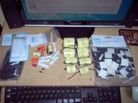
Huge number of crossover bits accumulating, but I'm learning as I go along, so we are not near the finished article yet. A Vifa or Morel tweeter with a 94mm metal front plate is beckoning along with some new coils, and I need to rolloff the bass a bit, I reckon.
Thanks to help from Planet 10, aka Dave, I have reinforced the cabinet front and back panels. Just 4X20cm pine cross battens per speaker on front and back to strengthen around holes. The battens don't even go to the edges, since I decided not to interfere with natural damping too much. Access was limited, so no chance of a proper brace really.
Huge number of crossover bits accumulating, but I'm learning as I go along, so we are not near the finished article yet. A Vifa or Morel tweeter with a 94mm metal front plate is beckoning along with some new coils, and I need to rolloff the bass a bit, I reckon.
Attachments
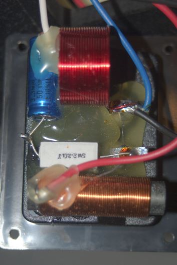
I see lots of problems. The crossover point for the tweeter is too high. The woofer needs a Zobel. The inductors shouldn't be parallel like that or the magnetic fields will feed into each other and make a sickening sound. Depending where your speakers are in relation to your ears, it can be motivated to switch polarities to "wrong", plus plus. If they are in front of you or below you, wire the tweeter "wrong". The dip in mid response is because of the flawed crossover design. You have a lot of work to do there, man.
For the tweeter, if you have no bigger inductor, add a 3.3 uf or 4 uf in parallel to the existing 3.3 uf. Put a 3-5 ohm resistor in series with the 0.27 mH inductor. A Zobel for the woofer could be 10 ohm and 10 uf. If you have a 0.5-1.0 mH inductor for the woofer, use that instead. If you have no such inductor, put a 10 ohm resistor in parallel with the 1.6 mH inductor. Move one of the inductors away with extension wiring. Tell me how it sounds.
For the tweeter, if you have no bigger inductor, add a 3.3 uf or 4 uf in parallel to the existing 3.3 uf. Put a 3-5 ohm resistor in series with the 0.27 mH inductor. A Zobel for the woofer could be 10 ohm and 10 uf. If you have a 0.5-1.0 mH inductor for the woofer, use that instead. If you have no such inductor, put a 10 ohm resistor in parallel with the 1.6 mH inductor. Move one of the inductors away with extension wiring. Tell me how it sounds.
Last edited:
Thankyou for that, strawberry. Yes, you are right! The two coils are probably way too close together and badly aligned for mutual effects...I now have taken it apart for a rebuild. The hot-glue softened in hot water. It may be the root of the top-end harshness.I see lots of problems. The crossover point for the tweeter is too high. The woofer needs a Zobel. The inductors shouldn't be parallel like that or the magnetic fields will feed into each other and make a sickening sound. Depending where your speakers are in relation to your ears, it can be motivated to switch polarities to "wrong", plus plus. If they are in front of you or below you, wire the tweeter "wrong". The dip in mid response is because of the flawed crossover design. You have a lot of work to do there, man.
For the tweeter, if you have no bigger inductor, add a 3.3 uf or 4 uf in parallel to the existing 3.3 uf. Put a 3-5 ohm resistor in series with the 0.27 mH inductor. A Zobel for the woofer could be 10 ohm and 10 uf. If you have a 0.5-1.0 mH inductor for the woofer, use that instead. If you have no such inductor, put a 10 ohm resistor in parallel with the 1.6 mH inductor. Move one of the inductors away with extension wiring. Tell me how it sounds.
I am looking into baffle-step correction. Which is sort of what your 10R adjustment amounts to. 1.6mH is kinda awkward except with 4.5 ohms on the 10" baffle. Lots to do, as you say. It's a bit borked really. No idea on an exact impedance correction for the woofer, but I'm guessing it's about 0.25mH Le. FWIW, the current tweeter is 0.05mH and Re of 6.2 ohms. Woofer Re is 6.0R.
This is all tremendously interesting.
Last edited:
infact your not far away from where i live, im in kent. maybe when ive finished my speakers you can pop over and have a listening session with a few beers, then you can let me know if they where as unpulloffable as you first supposed... be interesting to see if you hold to your originnal viewpoint 
Hi,
Edit : misunderstood the pictures .....
1.6mH on the bass/mid = some included baffle step, and as you've noted in
another thread zobelling the bass / mid will completely screw up its roll-off.
The bass unit looks like a paper coated Audax to me or possibly Elac.
Zobelling an attenuated tweeter is an accepted method of making
it sweeter, and of course you don't have to stick to zobel values.
Not saying the x/o can't be improved, it probably can, but not by conjecture.
Assumptions about driver roll-offs are exactly that and it is wise to assume
they are as such that the original driver phasing is correct, not incorrect.
Other than the correct point about inductor alignments, Strawberry's
musings are the usual nonsense that only illustrate just how little he
actually knows about practical x/o design. I'd suggest a thorough
perusal of the x/o designs at : Zaph|Audio, anyone open to and
willing to learn can learn a lot there, and elsewhere.
rgds, sreten.
Last edited:
- Status
- This old topic is closed. If you want to reopen this topic, contact a moderator using the "Report Post" button.
- Home
- Loudspeakers
- Multi-Way
- Restoring Monitor Audio R300 bookshelf speakers.