Keep us posted with your Grimm Clone. I do have W22 and DXT too and might be tempted one day.
I think MiniDSP has a new product which can do an inverse all-pass filter to complement the MiniDSP crossover ?
They call it 'rePhase FIR' which requires OpenDRC board.
www.minidsp.com/applications/advanced-tools/rephase-fir-tool
I think MiniDSP has a new product which can do an inverse all-pass filter to complement the MiniDSP crossover ?
They call it 'rePhase FIR' which requires OpenDRC board.
www.minidsp.com/applications/advanced-tools/rephase-fir-tool
I'm building a clone of Grimm LS1. Previously thought about Dutch & Dutch 8c who achieve about the same goals and liked how my cardboard models sounded. However, 8c requires at least 3 drivers to get meaningful output down to 60Hz or lower. LS1 on other hand allows you to do this with just 2 drivers. I never heard LS1 but general opinion seems to be they are good loudspeakers.
I tried to replicate the speakers as close as possible: I took the same dimensions, used the same middle stiffener as they do, also put as much insulation as possible. While I wasn't quite sure about the outcomes I cut a couple of the corners to reduce costs:
- Used Scan-Speak 22W/4534 instead of Seas W22EX001. They seems to have very close TS parameters, but Scans are 3x cheaper.
- Used poliester foam instead of natural wool.
- Used 18mm/ 3/4'' plywood instead of what looks like 1'' MDF on their images.
While I expected the project to go smoothly I faced several difficulties along the way.
LS1 speakers are mounted on two half cylinders. "Legs" turned to be very difficult to make. I initially thought about making them from sew pipes which are exactly 160mm wide - the depth of LS1 cabinets. Unfortunately, the plastic used to make sew pipes is very slippy. While this is expected - you really don't want waste to stick to the pipes - paint and vinyl do not stick to them securely either. Even if I sand the surface.
These legs can be made of solid or glued wood. Unfortunately, there is no carpenter near my house who can cut a 115cm/3.77ft long cylinder into two half-cylinders precisely. I called about 10 companies and to my surprise nobody wanted was ready to cut the rounded wood.
Currently I want to dismiss the idea of legs and simply have rounded edges. Along 3 or 4 sides. I will try to make from carton tubes or simply glue pieces of wood along the sides and ask the carpenter to round them as much as he can. This won't give me as round edges as LS1 have but it's better than nothing.
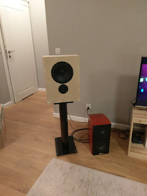
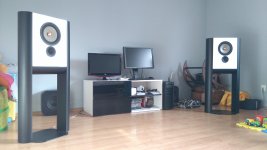
Here are my boxes standing on stands from Polk LSiM 703.
I probably made a mistake by ordering enclosure from plywood. I completely disliked the sound when I turned them for the first time. While the stereo-image was very clear and precise, the sound was rough and unclear. I had no desire to turn the volume up. Trying to figure out the cause of the poor sound I made half cylinders from carton and glued them to the sides. This made the sound much smoother but still it wasn't precise. I have Polk LSiM speakers turned to a completely active system and they played much smoother and detailed.
Spectrogram looked awful so I thought the box resonated heavily:
I glued some corner stiffeners and tightened front and back panels with six 160mm screws. Screws hugely changed the way speakers sounded when I knock on them.
Spectrogram also improved (Fourier, 600ms window):
Speakers started to sound much better now. Yet I'm not completely happy with the sound. Half cylinders still change the sound - make it less precise, but more smooth.
I tried to glue 3mm sheets of stiff resin used to insulate floors and machines. Something similar Harbeth uses for their speakers. The resin didn't improved the sound as much as hoped.
So, I'm currently at crossroads. Either drop this project entirely and build a Dutch&Dutch clone that sounded reasonably good even from cardboard boxes or make new enclosures for the LS1.
Do you have any ideas if enclosure made from MDF will resonate less? Any other ideas to stiffen-up current boxes?
Here are their boxes during assembly:
I tried to replicate the speakers as close as possible: I took the same dimensions, used the same middle stiffener as they do, also put as much insulation as possible. While I wasn't quite sure about the outcomes I cut a couple of the corners to reduce costs:
- Used Scan-Speak 22W/4534 instead of Seas W22EX001. They seems to have very close TS parameters, but Scans are 3x cheaper.
- Used poliester foam instead of natural wool.
- Used 18mm/ 3/4'' plywood instead of what looks like 1'' MDF on their images.
While I expected the project to go smoothly I faced several difficulties along the way.
LS1 speakers are mounted on two half cylinders. "Legs" turned to be very difficult to make. I initially thought about making them from sew pipes which are exactly 160mm wide - the depth of LS1 cabinets. Unfortunately, the plastic used to make sew pipes is very slippy. While this is expected - you really don't want waste to stick to the pipes - paint and vinyl do not stick to them securely either. Even if I sand the surface.
These legs can be made of solid or glued wood. Unfortunately, there is no carpenter near my house who can cut a 115cm/3.77ft long cylinder into two half-cylinders precisely. I called about 10 companies and to my surprise nobody wanted was ready to cut the rounded wood.
Currently I want to dismiss the idea of legs and simply have rounded edges. Along 3 or 4 sides. I will try to make from carton tubes or simply glue pieces of wood along the sides and ask the carpenter to round them as much as he can. This won't give me as round edges as LS1 have but it's better than nothing.
Here are my boxes standing on stands from Polk LSiM 703.
I probably made a mistake by ordering enclosure from plywood. I completely disliked the sound when I turned them for the first time. While the stereo-image was very clear and precise, the sound was rough and unclear. I had no desire to turn the volume up. Trying to figure out the cause of the poor sound I made half cylinders from carton and glued them to the sides. This made the sound much smoother but still it wasn't precise. I have Polk LSiM speakers turned to a completely active system and they played much smoother and detailed.
Spectrogram looked awful so I thought the box resonated heavily:
An externally hosted image should be here but it was not working when we last tested it.
I glued some corner stiffeners and tightened front and back panels with six 160mm screws. Screws hugely changed the way speakers sounded when I knock on them.
Spectrogram also improved (Fourier, 600ms window):
An externally hosted image should be here but it was not working when we last tested it.
Speakers started to sound much better now. Yet I'm not completely happy with the sound. Half cylinders still change the sound - make it less precise, but more smooth.
I tried to glue 3mm sheets of stiff resin used to insulate floors and machines. Something similar Harbeth uses for their speakers. The resin didn't improved the sound as much as hoped.
So, I'm currently at crossroads. Either drop this project entirely and build a Dutch&Dutch clone that sounded reasonably good even from cardboard boxes or make new enclosures for the LS1.
Do you have any ideas if enclosure made from MDF will resonate less? Any other ideas to stiffen-up current boxes?
Here are their boxes during assembly:
An externally hosted image should be here but it was not working when we last tested it.
I know the thing or two about Grimm Audio LS1. It took me more than two years to finish it and to fully understand its philosophy and all technical principles.
Do not cut the corners and use only genuine drivers. They have unique calm, clean and extremely resolving sound character, especially when driven with top-class Hypex electronics.
Loudspeaker cabinets are built with 25-mm thick MDF exactly following original dimensions and internal brace placement between drivers which is extremely important in order to destroy front and rear panel resonance modes.
Cabinets are damped with natural, untreated sheep wool.
Half-cylinder legs are indeed the hardest part of the project. The legs caused all my project to stall for long time and it wasted much money to finally do it (almost) right.
I did XLS10 cabinets poorly and internal pressure while testing excursion under 500W amplifier simply broke them apart!
What is more, I managed to integrate inside of that legs all necessary electronics with DLCP add-on for connecting source and with analog output for other channel monitors and LS1s clone subwoofers. I used Grimm TPR balanced cable for analog connections. Legs are mounted with neodymium mangnets and secured with screws - everything is just like in original LS1.
Hardware is only one part of the project. In order to get the most of it, all system must be very precisely measured, equalised and crossed-over exactly following design principles described in white paper. Any +/- 1dB difference in drivers tuning is easily noticeable with such extremely resolving audio playback system. It took large effort for me to estabilish great sounding filters set for my LS1.
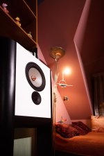
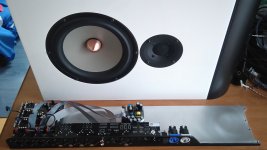
There is a few pictures of my clone from various stages of building. Not too many for now, in order to not violate Grimm's rights whom I managed to know personally and he and his company is really friendly, helpful and professional! *Ultra-wide-angle lens caused them to look fatter than in reality on third photo.
Do not cut the corners and use only genuine drivers. They have unique calm, clean and extremely resolving sound character, especially when driven with top-class Hypex electronics.
Loudspeaker cabinets are built with 25-mm thick MDF exactly following original dimensions and internal brace placement between drivers which is extremely important in order to destroy front and rear panel resonance modes.
Cabinets are damped with natural, untreated sheep wool.
Half-cylinder legs are indeed the hardest part of the project. The legs caused all my project to stall for long time and it wasted much money to finally do it (almost) right.
I did XLS10 cabinets poorly and internal pressure while testing excursion under 500W amplifier simply broke them apart!
What is more, I managed to integrate inside of that legs all necessary electronics with DLCP add-on for connecting source and with analog output for other channel monitors and LS1s clone subwoofers. I used Grimm TPR balanced cable for analog connections. Legs are mounted with neodymium mangnets and secured with screws - everything is just like in original LS1.
Hardware is only one part of the project. In order to get the most of it, all system must be very precisely measured, equalised and crossed-over exactly following design principles described in white paper. Any +/- 1dB difference in drivers tuning is easily noticeable with such extremely resolving audio playback system. It took large effort for me to estabilish great sounding filters set for my LS1.
There is a few pictures of my clone from various stages of building. Not too many for now, in order to not violate Grimm's rights whom I managed to know personally and he and his company is really friendly, helpful and professional! *Ultra-wide-angle lens caused them to look fatter than in reality on third photo.
Attachments
Last edited:
I know the thing or two about Grimm Audio LS1. It took me more than two years to finish it and to fully understand its philosophy and all technical principles.
They look really cool! Congrats on the finished project!
It seems that I'm mostly stuck with the box itself.
What MDF did you use? Is it a stiffer or softer one?
Did you make any measurements of the finished speaker? I'm most interested in the spectrogram.
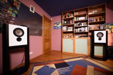
Regarding your question on why I started this particular project. I'm trying to cope with room reverberations. My room is about 40m2, wooden floors, painted walls. Reverberation times are quite high. Speakers that maintain directivity down to bass tend sound better than slim towers.
There are several approaches to controlling loudspeaker directivity. Wide baffle is one of them. Between wide speakers I really like how LS1 look. So I chose that particular project.
Thanks! I used best MDF available in Poland - Swiss Krono which is hard, heavy and rigid. I did some polar measurements but I have no spectograms / CSD characteristics of bare loudspeakers becouse my acoustic environment is noisy and reverbant. I consider such diagrams totally meaningless in such testing environment.
I also have wooden floor, what is more, my room is on the attic so it is real "bass-sucker". There is need to provide considerably more bass output into this room in order to bring back tonal balance but from the other side, I have no significant room modes. Waterfalls taken from listening place are amazingly clean (impossible to reach in typical rectangular room with rigid walls).
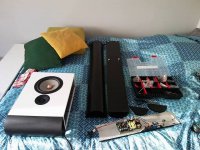
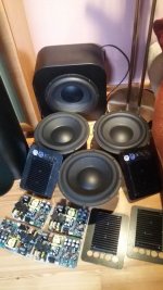
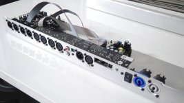
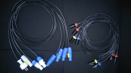
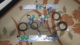
Here you can see a few iterations of internal electronics integration inside of the legs, and a set of my external DIY cabling. First were unpainted aluminium profiles with UCD400OEM's, my custom buffers and SMPS400. It was very bad idea to use these becouse lot of internal cabling, frequent issues with reliability, too little space and overall complexity. Now I switched to NC122MP and I relieved (fourth photo shows trimmed and painted profile ready for mounting new, small amplifier module. Last pic shows current efforts to build 4 subwoofer array in order to properly energize my room with low frequencies.
I also have wooden floor, what is more, my room is on the attic so it is real "bass-sucker". There is need to provide considerably more bass output into this room in order to bring back tonal balance but from the other side, I have no significant room modes. Waterfalls taken from listening place are amazingly clean (impossible to reach in typical rectangular room with rigid walls).
Here you can see a few iterations of internal electronics integration inside of the legs, and a set of my external DIY cabling. First were unpainted aluminium profiles with UCD400OEM's, my custom buffers and SMPS400. It was very bad idea to use these becouse lot of internal cabling, frequent issues with reliability, too little space and overall complexity. Now I switched to NC122MP and I relieved (fourth photo shows trimmed and painted profile ready for mounting new, small amplifier module. Last pic shows current efforts to build 4 subwoofer array in order to properly energize my room with low frequencies.
Attachments
Last edited:
I gave up making plywood cabinets sound clean. Thought about making them from MDF, but learned about EVA foam here on forum and gave it a try. The difference in one word is WOW.
Here is a spectrogram of speaker cabinets made from 40mm EVA-foam:
and that's a 39mm plywood+rubber cabinets:
Please ignore everything below 70Hz. There is a high-pass filter at 70Hz in both cases, but the sub was working during plywood measurements.
The difference is most noticeable in vocals. With EVA foam they are much more clean and natural. I made a quick video showing how do the speakers sound:
YouTube
Here is a spectrogram of speaker cabinets made from 40mm EVA-foam:
An externally hosted image should be here but it was not working when we last tested it.
and that's a 39mm plywood+rubber cabinets:
An externally hosted image should be here but it was not working when we last tested it.
Please ignore everything below 70Hz. There is a high-pass filter at 70Hz in both cases, but the sub was working during plywood measurements.
The difference is most noticeable in vocals. With EVA foam they are much more clean and natural. I made a quick video showing how do the speakers sound:
YouTube
1500Hz crossover seems to be a comprise due to the 22W metal woofer.
I use a different non-metalic woofer with the same 27TBCD/GB-DXT tweeter used in LS1. When tweeter is crossed to the woofer at 1500Hz the distortion plot looks this way:

Crossing the tweeter higher at 2000Hz improve things a lot:

Somehow distortion at lower frequencies causes problems higher in frequency band. I tried even the longest sweeps REW allows and the distortion is still there.
My recorder doesn't catch the difference, but its easy to hear it. The sound is much cleaner with a higher XO point. Even 1800 is enough.
Grimm Audio couldn't put XO so high due to the resonance in Seas Excel woofer. However, it is not clear for me why they didn't add a separate mid into the build or used a bigger horn for tweeter or used a paper cone woofer.
I use a different non-metalic woofer with the same 27TBCD/GB-DXT tweeter used in LS1. When tweeter is crossed to the woofer at 1500Hz the distortion plot looks this way:
Crossing the tweeter higher at 2000Hz improve things a lot:
Somehow distortion at lower frequencies causes problems higher in frequency band. I tried even the longest sweeps REW allows and the distortion is still there.
My recorder doesn't catch the difference, but its easy to hear it. The sound is much cleaner with a higher XO point. Even 1800 is enough.
Grimm Audio couldn't put XO so high due to the resonance in Seas Excel woofer. However, it is not clear for me why they didn't add a separate mid into the build or used a bigger horn for tweeter or used a paper cone woofer.
This is interesting finding which doesn't correspond with my amateur measurements which are a shame to publish today. 2nd order distortion from DXT tweeter always was step higher than in Excel woofer for this particular design.
Low crossover point in LS1 is indeed chosen due to 1/3x break-up frequency avoidance rule. As I always explain, we need to equalize this peak to flat and then leave it well behind designed passband.
But such unusually low division point is not chosen only from this reason. LS1 was designed as full-range 2-way for studio monitoring duties. 8+1 loudspeakers (common in this environment) are always flawed by the design from dispersion consistency point of view which is not so relevant in highly controlled studio environment and this wasn't strong design point until they realized that it also can serve in domestic conditions. At 1.5kHz 8-inch Excel woofer already starts to beam, whereas DXT still hasn't any directional attributes of its waveguide. In typical reflective listening room this directivity step is easy to spot when crossover point is too high, especially for metal drivers who tend to loose their wide dispersion characteristics quicker than soft-cones. I did once experiment with crossover and setting it higher made the overall sound impression worse, it became honky and harsh due to increasing directivity jump between quickly narrowing Excel and still wide-radiating DXT. Natural division frequency for DXT starts around 2.8kHz or higher which corresponds with 5-inch woofer for its companion. Low division point for 8+1 design also improves off-axis lobing for natural reasons.
Last edited:
The thing that bothers me in my also amateur-ish measurements is that low XO point causes distortion higher in frequency band. I tried slow and fast sweeps and it's always there. Sometimes it is flat and wide like on the pictures above, sometimes it has a structure like that:

But it's always there. Bringing crossover higher in frequency solves the problem and I don't see that distortion any more.
I have no idea what causes that distortion.
But it's always there. Bringing crossover higher in frequency solves the problem and I don't see that distortion any more.
I have no idea what causes that distortion.
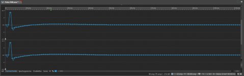
You can do it simply.
Generate a dirac at your target frequency, here 96k 32b. Prepare an allpass (DDMF IIEQ pro here, equilibrium can do it also).

Apply it.

Zoom the waveform to the max to be able to trim.

Time reverse it.
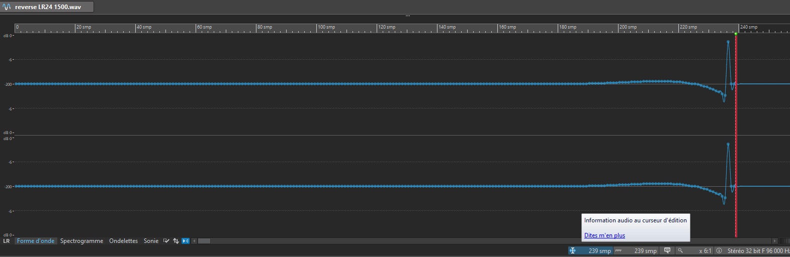
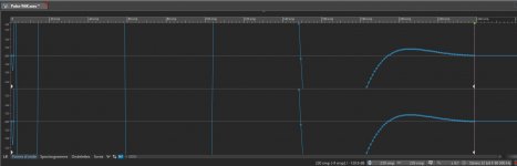
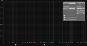
You now just have to convert a wav to whatever FIR format your want. As you can see above, it is currently 239 taps to get it under -200 dBFS.
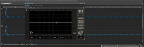
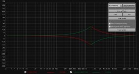
Import through REW, you see zoomed FR is perfect :

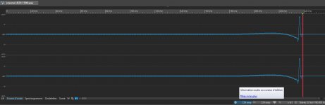
And phase is perfectly mirrored :

That way, you can also easily try manual windowing, etc. and see in REW how much error is introduced by doing that.
Generate a dirac at your target frequency, here 96k 32b. Prepare an allpass (DDMF IIEQ pro here, equilibrium can do it also).
Apply it.
Zoom the waveform to the max to be able to trim.
Time reverse it.
You now just have to convert a wav to whatever FIR format your want. As you can see above, it is currently 239 taps to get it under -200 dBFS.
Import through REW, you see zoomed FR is perfect :
And phase is perfectly mirrored :
That way, you can also easily try manual windowing, etc. and see in REW how much error is introduced by doing that.
Attachments
Last edited:
- Status
- This old topic is closed. If you want to reopen this topic, contact a moderator using the "Report Post" button.
- Home
- Loudspeakers
- Multi-Way
- Understanding Grimm Audio XO