Hello everyone,
Has anyone implemented a delay line from
E. J. Jordan's article "Loudspeaker Stereo Techniques"?
http://www.ejjordan.co.uk/PDFs/Jordan_WW_Feb_71.pdf
What are the results? How many speakers are really required per meter of sound stage? Or rather per some angle?
I suppose the way to go here is line level (analog of digital) delay and an amplifier per speaker.
Hello everyone,
Has anyone implemented a delay line from
E. J. Jordan's article "Loudspeaker Stereo Techniques"?
http://www.ejjordan.co.uk/PDFs/Jordan_WW_Feb_71.pdf
What are the results? How many speakers are really required per meter of sound stage? Or rather per some angle?
I suppose the way to go here is line level (analog of digital) delay and an amplifier per speaker.

I subscribe to the above questions
What is the right way of calculating directivity for such array with positions of each driver and their phase?
I second the above questions, where are all wise men of this forum?

I suppose that it was a kind of 1971 soundbar
a bit like Niro Nakamichi's "1000" Surround bar:
Niro Nakamichi 1000 Surround Bar First Look — Reviews and News from Audioholics
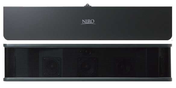
only deeper, with at least 2x2 speakers side-firing, and turned on it's back, then mounted on wall
a bit like Niro Nakamichi's "1000" Surround bar:
Niro Nakamichi 1000 Surround Bar First Look — Reviews and News from Audioholics
only deeper, with at least 2x2 speakers side-firing, and turned on it's back, then mounted on wall
Last edited:
A couple of comments on the Jordan system.
He gets the delay line notion from the typical model of propagation delay as a series of sequentially linked masses and compliances. The electrical equivalent would be an L C ladder network. Such a ladder network would have a propogation delay, but at the same time it has to have a low pass nature. Converting it to a sequence of full range drivers with L's in between is not the same and is not exactly a delay line. Each L can provide phase shift but not without considerably response rolloff. In general you will get 3 dB of loss at every 45 degrees of phase shift. In other words it will be much better at rolling off treble (with more rolloff for each sequential unit) than in providing delay. It will not provide broadband delay from unit to unit so it can not operate as described.
Put this aside and consider a full active DSP based version of it. It would be easy to use this technology to give broad band sequential delay from unit. What would you achieve? In the end the sequential delay is identical to angling the far end of the delay further away in the room. Since you feed both the left end and the right end you effectivly have two lines with the left aiming towards the back right corner of the room and the right line facing back to the left. The effective angle comes from the ratio of lateral propogation speed to the speed of sound. The backwards tilt is simply the arctangent of the speed of sound divided by the lateral propagation speed. If they were equal, for example, the lines are effectivly angled back 45 degrees.
I'm not sure why this would be some ideal system. I guess part of the appeal is the thought that left and right are both fed to a common system and mixed signals radiate from some proportionate mid point. This notion is, of course, false.
As to modeling it, all multi-element line arrays are modeled by summing the vector output of each element with regard to the geometry between the various points and the observation point. Whether you have the backwards angled case or the electrically delayed case you would be modeling a conventional line array with a sequential phase rotation for each adjacent element. In the far field the two cases would be identical. In the near field they would be similar.
This was all explained in my paper on the subject.
AES E-Library Discrete-Element Line Arrays-Their Modeling and Optimization
David S.
What would you achieve? In the end the sequential delay is identical to angling the far end of the delay further away in the room.
David S.
Of course they are not identical. Because of the front wall reflection is absent as suggested in the design. That will not happen if you start angling them across the room.
Why is this ideal:
It provides two horisontal plane waves crossing at the listening position. This is the principal and fundamental assumption of the stereo system, and it is satisfied with this design. Of course the wave front is not plain in vertical dimension, but stereo is horisontal only according to the scriptures.
- Elias
this sounds reasonable!
A couple of comments on the Jordan system.
...
What would you achieve? In the end the sequential delay is identical to angling the far end of the delay further away in the room. Since you feed both the left end and the right end you effectivly have two lines with the left aiming towards the back right corner of the room and the right line facing back to the left. The effective angle comes from the ratio of lateral propogation speed to the speed of sound. The backwards tilt is simply the arctangent of the speed of sound divided by the lateral propagation speed. If they were equal, for example, the lines are effectivly angled back 45 degrees.
...
Whether you have the backwards angled case or the electrically delayed case you would be modeling a conventional line array with a sequential phase rotation for each adjacent element. In the far field the two cases would be identical. In the near field they would be similar.
This was all explained in my paper on the subject.
AES E-Library Discrete-Element Line Arrays-Their Modeling and Optimization
45 degrees curvature to the back? sounds familiar... yes - now it's more clear, it sounds just like CBT of Don Keele!
now read this:
But neither is actually "constant directivity". CBT is only constant beam height, the horizontal is not constant but falls just like any piston source. IMO they should be placed on their sides, or better yet just make a constant beam width in both directions! Now there is an idea!
wow! doesn't it look familiar?
An externally hosted image should be here but it was not working when we last tested it.
the curvature and power tapering in CBT array are just instead of a proper delay line
looks like old uncle Ted outsmarted the gurus of today as early as in 1971
outsmarted because He showed how to make such horizontal array for stereo not just for center channel speaker
Last edited:
To what purpose do you present such witty sarcasm?
I second the above questions, where are all wise men of this forum?
To what purpose do you present such witty sarcasm?
to bring the wise men in here, because otherwise (without some teasing) none of them would ever bother and the thread would be long dead by now and You would never even know that there was one
in this case it was success because my sarcasm has attracted Dave S. who contributed with a very insightful post

I would really prefer to refrain from using such methods as sarcastic teasing but with those people such methods are really indispensable

they are quite like little children, a bit of psychological manipulation is indispensable
...
Each L can provide phase shift but not without considerably response rolloff. In general you will get 3 dB of loss at every 45 degrees of phase shift. In other words it will be much better at rolling off treble (with more rolloff for each sequential unit) than in providing delay. It will not provide broadband delay from unit to unit so it can not operate as described.
...
I guess part of the appeal is the thought that left and right are both fed to a common system and mixed signals radiate from some proportionate mid point. This notion is, of course, false.
underlines mine
so thanks to Dave's expert knowledge we know what cannot work
so how could such delay line setup be realized otherwise?
because Jordan wrote expressly in the 1971 article that such delay line system had been prototyped and tested and that it worked
any ideas?
This was all explained in my paper on the subject.
AES E-Library Discrete-Element Line Arrays-Their Modeling and Optimization
David S.
so this is the paper?
McIntosh Loudspeaker Division Part 2
Jordan's work was predated by Peter Walker, by at least a decade, probably two...
Walker's ideas found practical implemention in mono, of course, in the form of the ESL63 where delay lines are incorporated to drive the "rings" so that the speaker creates a spherical wave from the flat ESL panel... (not sure it succeeds sonically though). Those who have read his publications may come across the earlier idea(s).
_-_-bear
Graf,
you picture is the REVERSE of the curve from the delay line fed array, where the L signal enters from the Left and the Right signal enters from the RIGHT... the sound emanates FIRST from the ends, then is later heard sequentially from driver elements heading to the other end...
_-_-bear
you picture is the REVERSE of the curve from the delay line fed array, where the L signal enters from the Left and the Right signal enters from the RIGHT... the sound emanates FIRST from the ends, then is later heard sequentially from driver elements heading to the other end...
_-_-bear
Jordan's work was predated by Peter Walker, by at least a decade, probably two...
...
Those who have read his publications may come across the earlier idea(s).
but did Walker invent passive delay lines? of course not, He didn't even invent an application of it to electrostatic panel speaker - Kellog and Shorter did it, He just invented this particular ESL application, for more history see below
and Jordan invented (or at least claimed to invent) a particular application of it to a horizontal array of dynamic speakers
so can we really say that Jordan was indebted to Walker? I don't think so, they were just two very talented contemporaries and the ideas were up in the air at the time
it is often overlooked fact that Jordan presented His ESL design for Goodmans at the same time as QUAD, an overlooked fact because Goodmans was not interested in putting an ESL on the market
and precisely speaking QUAD ESL-63 as first practical application of passive delay lines to electrostatic panel speaker was revealed in 1979 and released in 1981
strangely enough rather a decade after the 1971 article by Jordan
some history:
Development of the Quad ESL '63 - A Short Patent History
The development of the speaker that became known as the Quad ESL '63 is largely the story of a search for greater power handling and greater output plus linearity at the low frequency extremes. It's designation as the '63 is a matter of conjecture, but most people accept as fact that 1963 was the year in which Peter Walker made his first notebook entries about the design that became the '63. It was a long development phase - 18 years in all, but as Walker himself said in 1994:
"It's like the ESL 63 loudspeaker. It took us 18 years to develop but it wasn't 18 years every day. [Laughs] Not at all."
Walker admits to leaning rather heavily on the work of Shorter from the BBC and Kellogg in his development of the ESL 63. He is plain about this in his 1979 AES lecture (Page 2, Page 3), which was about the first occasion that the '63 had a public outing. In that lecture, he says:
"So, finally, what is new about all this? Really, it is a lot of old ideas fitted together. Kellogg in 1929 proposed the connection of a series of electrostatic elements by inductors as a delay line. His idea was to improve efficiency and reduce the power requirement from amplifiers. Shorter of the BBC took out a patent in 1941 describing the connection of a series of annular rings using resistors and Janszen, in 1953, suggested variations on the same theme.
In effect therefore, all I have done is to collect these ideas and add a little work which says that if you can make the device acoustically transparent, then the performance can be predicted. We think this is very important since it enables correction to the performance to be made very easily and after simple laboratory measurements." Peter Walker, June, 1979 AES British Section.
see: ESL63History
anyway - this input from You in this thread is very important thank You!
because it reminds us about passive delay lines for ESL - most probably Jordan's delay lines were of the same kind
if such lines worked in case of ESLs then why not in case of an array of dynamic speakers?
then probably they were not just much better at rolling off treble (with more rolloff for each sequential unit) than in providing delay
how did QUAD's delay lines for ESL look alike?
Graf,
you picture is the REVERSE of the curve from the delay line fed array, where the L signal enters from the Left and the Right signal enters from the RIGHT...
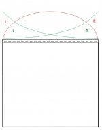
concave? I believe that for stereo it would look even more complicated, more like two horizontal convex CBTs arrays both stretching across the whole width of the room and crossing in the middle
I will post a scheme later
regards,
graaf
Attachments
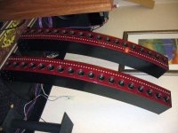
how did QUAD's delay lines for ESL look alike?
ps.
http://www.diyaudio.com/forums/planars-exotics/61220-quad-esls-delay-lines.html
http://www.diyaudio.com/forums/planars-exotics/46145-esl-63-what-type-coil-delay-line.html
it is claimed that the delay is set to be equal to the delay corresponding to the distance between the center and the edge of the speaker assuming speed of sound
could it be that in case of the Jordan array we must set total delay corresponding to the width of the room and speed of sound as well?
QUAD delay line:
An externally hosted image should be here but it was not working when we last tested it.
An externally hosted image should be here but it was not working when we last tested it.
Graaf, yes the reverse of the two examples you show.
The second example you show is intended to keep the HF energy constant back
at the listening position IN THE CASE where the array does NOT go floor to ceiling AND the array is not sufficiently high & the listener is "too far back" to be in the zone where there is "equal energy" (sufficient HF dispersion...).
If the delay lines are set so that they are equal to the speed of sound then the wave looks like a 45 degree (of course it has discrete steps in reality - ha ha) wall coming at you from either side, sweeping from the front of the room and pushing past you to the back - the last energy reaching you from the far opposite side. Not curved.
Of course one could curve it... but that is another story.
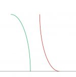
The curve would always be concave looking AT it from the listening position... looking INTO a bowl in effect.
The all pass filter that presumably would be used, on paper and in theory, ought to be free of HF rolloff, but in practice, especially at speaker level probably does have rolloffs - I have never tried to build such and don't have the practical experience to know for sure.
Seems like one could make an active implementation free of HF amplitude rolloff though. A lot of elements...
If ur using CD or digital source, it would be much easier to implement in terms of being lossless, but that is beyond my experience and ability to design at this point in time. If there are any folks reading who find such a thing well within their design abilities, then contact me privately! I am interested in talking about it.
_-_-bear
PS. thanks for pointing to that AES talk by Peter Walker! I was unaware of it. Good information!
The second example you show is intended to keep the HF energy constant back
at the listening position IN THE CASE where the array does NOT go floor to ceiling AND the array is not sufficiently high & the listener is "too far back" to be in the zone where there is "equal energy" (sufficient HF dispersion...).
If the delay lines are set so that they are equal to the speed of sound then the wave looks like a 45 degree (of course it has discrete steps in reality - ha ha) wall coming at you from either side, sweeping from the front of the room and pushing past you to the back - the last energy reaching you from the far opposite side. Not curved.
Of course one could curve it... but that is another story.
The curve would always be concave looking AT it from the listening position... looking INTO a bowl in effect.
The all pass filter that presumably would be used, on paper and in theory, ought to be free of HF rolloff, but in practice, especially at speaker level probably does have rolloffs - I have never tried to build such and don't have the practical experience to know for sure.
Seems like one could make an active implementation free of HF amplitude rolloff though. A lot of elements...
If ur using CD or digital source, it would be much easier to implement in terms of being lossless, but that is beyond my experience and ability to design at this point in time. If there are any folks reading who find such a thing well within their design abilities, then contact me privately! I am interested in talking about it.
_-_-bear
PS. thanks for pointing to that AES talk by Peter Walker! I was unaware of it. Good information!
Last edited:
The second example you show is intended to keep the HF energy constant back
at the listening position IN THE CASE where the array does NOT go floor to ceiling AND the array is not sufficiently high & the listener is "too far back" to be in the zone where there is "equal energy" (sufficient HF dispersion...).
yes, I have read the CBT paper
Graaf, yes the reverse of the two examples you show.
...
The curve would always be concave looking AT it from the listening position... looking INTO a bowl in effect.
so it will look/sound like the red curve - not the green on the scheme below?
the why Keele's CBTs are convex not concave?
PS. thanks for pointing to that AES talk by Peter Walker! I was unaware of it. Good information!
you're welcome
Attachments
- Status
- This old topic is closed. If you want to reopen this topic, contact a moderator using the "Report Post" button.
- Home
- Loudspeakers
- Multi-Way
- E. J. Jordan Delay Line