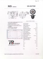
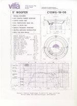
I have Vifa C13WG-19-08 woofer and a TB 28-847SE tweeter that I'm building a two way vented system with. I wanted to make a 6db filter for these two but I'm not sure if that's a valid choice with these drivers. Any suggestion on what type of filter and crossover frequency that would work well is greately appreciated.
Attachments
Last edited:
a crossover freq of ~2KHz should be OK. Why 6dB? It would probably work fine, but if you play at high volume I'd go with 12dB to protect the tweeter. Alternatively 6db on the woofer will let you factor in BSC easily, & 12dB on the tweeter (inverse polarity) will give protection...
")
Crossover must be designed with acoustical slope in mind and not electrical slope. The acoustical slope is the sum of the electrical slope (=filter) + natural behavior of the driver ***on baffle***.
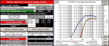
You could easily achieve 4th order LR with only 2 components. As an example I'm attaching a simulated response of a Seas 27TBFC/G on a specific baffle: the response has an acoustic 4th order slope at 2K with only a cap and an inductor.
With a single cap you get a bump at resonance only 15 dB under.
Ralf
Attachments
Yes, you should measure the driver on the baffle. However there are some methods in order to simulate the response, you need to have at least a published frequency response (usually on an infinite baffle or on the IEC one) - and you have them.
Read here: Using FRD Consortium tools to design a speaker
or something similar: software (go down the page)
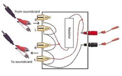
I suggest you to measure at least the TS woofer's data and the impedance of both drivers. This is easily done with a simple jig: loudspeaker-measurement-jig
I see that there aren't anymore images in the above link. Here you can see a drawing of the jig.
Ralf

Read here: Using FRD Consortium tools to design a speaker
or something similar: software (go down the page)
I suggest you to measure at least the TS woofer's data and the impedance of both drivers. This is easily done with a simple jig: loudspeaker-measurement-jig
I see that there aren't anymore images in the above link. Here you can see a drawing of the jig.
Ralf
Attachments
I don't check the fullrange forum but I saw by chance your other thread about the measures of the woofer. I offer you a couple of considerations.
1) It appears you have some (very) old woofers. The surround could have changed significantly its mechanical properties, changing VAS, FS and Qts values (they all are tied together). You need at least to try driving the drivers hard for some time: put a sine wave of 20-30 Hz on them for 1-2 days (you may not hear any sound but you have to see the cone move some mm). Then re-measure the drivers.
2) Measure the impedance of the drivers in box. Your WT3 should do that. You need this measure for crossover simulations (see my last post).
3) T/S parameters are only needed for choosing the right box, and don't affect the crossover as your crossover frequency will stay in the 2K Hz range.
4) The impedance measure of the woofer in box will tell you also the tuning frequency: it is the minimum impedance measure between the two high peaks.
Ralf
- Status
- This old topic is closed. If you want to reopen this topic, contact a moderator using the "Report Post" button.
- Home
- Loudspeakers
- Multi-Way
- Crossover suggestions