I wanted to accomplish a few different things with this build after I gave my previous speakers to a friend (new furniture required some downsizing).
First, reuse the Acoustic Elegance TD15Hs I had stuffed in my previous cabinets. I gave my friend a set of JBL 2235Hs in those cabinets.
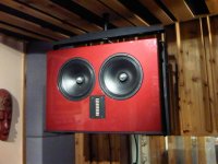
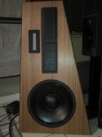
Second, I wanted to try a 2-way using something a bit different. I like the idea of a ribbon, but most do not play very low on the spectrum, so when I started looking at the Beyma TPL-150 I though I just might be able to stretch the AE TD15H up high enough to meet the minimum crossover of 1 kHz for the Beyma.
The Beyma also lists 1 kHz with a 2nd order crossover! That gave me some leeway and I figured I start the first try at 1.2 kHz and see what I get.
Next, cabinet construction. Starting fresh gave me the opportunity to try a different construction technique - Constrained Layer Damping using Green Glue and Baltic Birch.
The cabinets would be about 5 cubic feet internally and I used the Golden Ratio to make a simple rectangular box.
I ordered 5 sheets of 5' by 5' 3/4" Baltic Birch plywood from a local mill. A friend rolled his table saw down the street to help cut the wood. I spent a lot of time with a CAD drawing package to get all the pieces worked out and we spent the day cutting wood.
After I cut everything I had other work holding up the project. It wasn't until a few days later that I discovered a bad error. The plywood was not 3/4" thick, but closer to .675" (about 18 mm)!
This was a huge problem because the CLD cabinet was critically designed to be a box within a box with a gap of 0.020" (about 1/2 mm) between the two boxes for the CLD Green Glue.
I put the project on hold while I contemplated how to work around the problem. Finally, I just figured I would punt and I assembled the outer shell.
I had intended to build from the inside out, but I needed a different tact. So I built the outer box so the front and back would fit and then applied Green Glue to each panel on the inside and laid the inner panels over that.
Since the dimensions were no longer perfect I just left all the gaps in the corners and filled the larger ones then glued and nailed corners on the inside edges to attach each inner panel to the next in a ridged fashion.
The result is an inner cabinet that floats on a thin layer of Green Glue. No nails penetrate the inner box to the outer box, so the only common point will be the front panel.
The front panel is simply two layers of 18 mm Baltic Birch glued together with Tightbond glue.
The front panels are then glued to the inner panel edges with a form of Liquid Nails (polyurethane) . The outer cabinet is bonded to the sides of the front panel with yellow glue. Then the front panel is nailed using 16 gauge brads from a nail gun to hold it in place while the glue does its job.
The finished cabinet is really very heavy and dead! Knocking on it is like knocking on a tree. I don't know the weight of the cabinet, but I am guessing 60 to 70 pounds without drivers.
After cutting all the wood I first glued the front panels together and the let those dry. When I got back to the project I laid out the holes for the ports, TD15H, and TPL-150 on the two front panels.
I used a router for the woofer and the ports since I already made a metal circle template for that, but the Beyma was a rectangle, so I made a fixture on my Bridgeport and cut those holes with the mill.
I squared off the inside edges with a small Japanese hand saw.
After the milling is done I screwed and clamped a scrap piece of plywood to the backside so when I use the router for the woofer opening I would not have the center hole drop out.
Here is my home made router jig and several passes later I get the recessed and actual cut into the front plate:
And now...
Next is the ports first pass...
And then I completed the routing, which had three levels of cuts, to fit the Parts-Express flares. I used the inside flares and cut the openings so the ports press fit into the front panel. After the cabinet is veneered I will glue them in place.
First, reuse the Acoustic Elegance TD15Hs I had stuffed in my previous cabinets. I gave my friend a set of JBL 2235Hs in those cabinets.
Second, I wanted to try a 2-way using something a bit different. I like the idea of a ribbon, but most do not play very low on the spectrum, so when I started looking at the Beyma TPL-150 I though I just might be able to stretch the AE TD15H up high enough to meet the minimum crossover of 1 kHz for the Beyma.
The Beyma also lists 1 kHz with a 2nd order crossover! That gave me some leeway and I figured I start the first try at 1.2 kHz and see what I get.
Next, cabinet construction. Starting fresh gave me the opportunity to try a different construction technique - Constrained Layer Damping using Green Glue and Baltic Birch.
The cabinets would be about 5 cubic feet internally and I used the Golden Ratio to make a simple rectangular box.
I ordered 5 sheets of 5' by 5' 3/4" Baltic Birch plywood from a local mill. A friend rolled his table saw down the street to help cut the wood. I spent a lot of time with a CAD drawing package to get all the pieces worked out and we spent the day cutting wood.
After I cut everything I had other work holding up the project. It wasn't until a few days later that I discovered a bad error. The plywood was not 3/4" thick, but closer to .675" (about 18 mm)!
This was a huge problem because the CLD cabinet was critically designed to be a box within a box with a gap of 0.020" (about 1/2 mm) between the two boxes for the CLD Green Glue.
I put the project on hold while I contemplated how to work around the problem. Finally, I just figured I would punt and I assembled the outer shell.
I had intended to build from the inside out, but I needed a different tact. So I built the outer box so the front and back would fit and then applied Green Glue to each panel on the inside and laid the inner panels over that.
Since the dimensions were no longer perfect I just left all the gaps in the corners and filled the larger ones then glued and nailed corners on the inside edges to attach each inner panel to the next in a ridged fashion.
The result is an inner cabinet that floats on a thin layer of Green Glue. No nails penetrate the inner box to the outer box, so the only common point will be the front panel.
The front panel is simply two layers of 18 mm Baltic Birch glued together with Tightbond glue.
The front panels are then glued to the inner panel edges with a form of Liquid Nails (polyurethane) . The outer cabinet is bonded to the sides of the front panel with yellow glue. Then the front panel is nailed using 16 gauge brads from a nail gun to hold it in place while the glue does its job.
The finished cabinet is really very heavy and dead! Knocking on it is like knocking on a tree. I don't know the weight of the cabinet, but I am guessing 60 to 70 pounds without drivers.
After cutting all the wood I first glued the front panels together and the let those dry. When I got back to the project I laid out the holes for the ports, TD15H, and TPL-150 on the two front panels.
I used a router for the woofer and the ports since I already made a metal circle template for that, but the Beyma was a rectangle, so I made a fixture on my Bridgeport and cut those holes with the mill.
I squared off the inside edges with a small Japanese hand saw.
An externally hosted image should be here but it was not working when we last tested it.
An externally hosted image should be here but it was not working when we last tested it.
An externally hosted image should be here but it was not working when we last tested it.
After the milling is done I screwed and clamped a scrap piece of plywood to the backside so when I use the router for the woofer opening I would not have the center hole drop out.
An externally hosted image should be here but it was not working when we last tested it.
Here is my home made router jig and several passes later I get the recessed and actual cut into the front plate:
An externally hosted image should be here but it was not working when we last tested it.
An externally hosted image should be here but it was not working when we last tested it.
And now...
An externally hosted image should be here but it was not working when we last tested it.
An externally hosted image should be here but it was not working when we last tested it.
Next is the ports first pass...
An externally hosted image should be here but it was not working when we last tested it.
And then I completed the routing, which had three levels of cuts, to fit the Parts-Express flares. I used the inside flares and cut the openings so the ports press fit into the front panel. After the cabinet is veneered I will glue them in place.
An externally hosted image should be here but it was not working when we last tested it.
With the fronts done I needed to build the cabinets. After discovering that all the wood was not 3/4" I was disheartened and almost gave up. My girlfriend kept at me to build them so I put the outer shell together.
I draged them into the family room to get them out of the garage and see what they looked like. They were huge!
I was very disheartened by the huge size and how they looked in our new living room (we just got all new leather sofas). I did not think they looked good in our room.
I was ready to can the project and got to the point where I was arguing with my girlfriend. I thought they were too much, but my girlfriend kept telling me to just finish them and I would be happy. We finally just stopped speaking about it and the next day I just decided to do it anyway - which pleased my girl.
So here we go...
I used the mill again with a 1/2" mill to cut out the two internal shelves.
With all the parts cut and routed I took a deep breath and started the inside panel assembly. I used hope as my strategy, or maybe I was smoking hope!
First panels were the inside top and bottoms. Green Glue was applied as per the manufacture directions. The Green Glue comes in large tubes and you need a large gun to dispense them. It took about one tube per cabinet.
Now the back...
Next are the side panels, which required clamps to hold in place...
The internal shelves are installed and the inside corners are joined with a 1" by 1" hardwood that is glued and nailed into every inside corner.
Finally, urethane glue is added to the inside edges where they contact the front baffle.
The outside edges of the front baffle are glued with yellow wood glue and the whole panel cross nailed into place.
The final assembly step was routing all the edges with a router bit with a bearing on the end. This cuts all the edges flush to each panel. A final sand and the cabinet is ready for the crossovers, stuffing, and drivers. Getting close to making sound!
The crossovers were hand assembled onto 1/16" fish paper. The design includes a Zobel for the woofer and a 7 dB pad on the Beyma.
After the crossovers were installed I added Acusta-Stuff to about 50% of the inside panels. The back panel gets most of it and then the sides.
Ports are installed last. Ports were cut to 37 Hz, well that was what I calculated.
I draged them into the family room to get them out of the garage and see what they looked like. They were huge!
I was very disheartened by the huge size and how they looked in our new living room (we just got all new leather sofas). I did not think they looked good in our room.
I was ready to can the project and got to the point where I was arguing with my girlfriend. I thought they were too much, but my girlfriend kept telling me to just finish them and I would be happy. We finally just stopped speaking about it and the next day I just decided to do it anyway - which pleased my girl.
So here we go...
I used the mill again with a 1/2" mill to cut out the two internal shelves.
An externally hosted image should be here but it was not working when we last tested it.
An externally hosted image should be here but it was not working when we last tested it.
With all the parts cut and routed I took a deep breath and started the inside panel assembly. I used hope as my strategy, or maybe I was smoking hope!
First panels were the inside top and bottoms. Green Glue was applied as per the manufacture directions. The Green Glue comes in large tubes and you need a large gun to dispense them. It took about one tube per cabinet.
An externally hosted image should be here but it was not working when we last tested it.
An externally hosted image should be here but it was not working when we last tested it.
Now the back...
An externally hosted image should be here but it was not working when we last tested it.
Next are the side panels, which required clamps to hold in place...
An externally hosted image should be here but it was not working when we last tested it.
The internal shelves are installed and the inside corners are joined with a 1" by 1" hardwood that is glued and nailed into every inside corner.
Finally, urethane glue is added to the inside edges where they contact the front baffle.
An externally hosted image should be here but it was not working when we last tested it.
The outside edges of the front baffle are glued with yellow wood glue and the whole panel cross nailed into place.
An externally hosted image should be here but it was not working when we last tested it.
The final assembly step was routing all the edges with a router bit with a bearing on the end. This cuts all the edges flush to each panel. A final sand and the cabinet is ready for the crossovers, stuffing, and drivers. Getting close to making sound!
The crossovers were hand assembled onto 1/16" fish paper. The design includes a Zobel for the woofer and a 7 dB pad on the Beyma.
An externally hosted image should be here but it was not working when we last tested it.
After the crossovers were installed I added Acusta-Stuff to about 50% of the inside panels. The back panel gets most of it and then the sides.
Ports are installed last. Ports were cut to 37 Hz, well that was what I calculated.
An externally hosted image should be here but it was not working when we last tested it.
First thing we did was listen. This violates my rule of measure, measure, measure, but we had a movie to watch, so I dragged out the tube amp and popped on Shawn Colvin to get a listen.
My first impression was the Beyma was too padded down. I don't believe in the theory of breaking in drivers much, so I was a little disappointed, but they were playing music!
The next thing I did was reset all the tone controls to neutral. The bass was much better than the last cabinet. In fact, it was a whole lot better! Hmm, the cabinet was a bit smaller than the old one, but the bass was deeper and louder. I'll buy it anyways.
I turned up the treble to compensate for the loss and we watched our movie.
Ran more music into it and we listened critically...
The sweet spot was much wider with the 2-way Beyma than the 3-way Audax PR170M and the Morel MDT-37 I was using. That was expected from the data sheet and confirmed by listening.
Clarity was excellent. The ribbon was exactly what they claim they are. Score again!
We let the music roll and later that evening I started to notice that the treble seemed louder. I can't say if it just me getting used to the new speakers or if the Beymas were changing (loosening up) as time went on, but I liked the result.
The next day I had to run a few tests just to get a baseline.
First was the impedance test using the Woofer Tester 2...
The impedance was not perfect and the true resonance of the port was a little lower than planned, but only by one or two Hz.
Next was a full range SPL plot at about 1 meter:
This tells me that the Beyma could go up about 2 or 3 dB as suspected. The plot also mirrors the published data for the Beyma very well. This gives me a warm fuzzy with the testing. This is my first time using HolmImpulse and it looks like a great tool.
I did an ad-hoc off axis plot that seemed to show a dip just after the 1 kHz point. Unfortunately it got erased and I need to do a better job with a formal off-axis series of tests.
Everything is very good with the speaker, but the Achilles' heel of the design is going to be the off-axis response. I am pushing the limits here and I recognize that this may be a problem.
I am considering adding the horns to the Beymas to get a little better directionality and drop the crossover point to 1 kHz if needed to cover that dip (if it really exists).
The problem with the off-axis measurement I did was proximity to other walls and a tile floor that limits what I am doing.
At some point I will rerun those tests in a structured way and post those results - good or bad - when I get them.
My first impression was the Beyma was too padded down. I don't believe in the theory of breaking in drivers much, so I was a little disappointed, but they were playing music!
The next thing I did was reset all the tone controls to neutral. The bass was much better than the last cabinet. In fact, it was a whole lot better! Hmm, the cabinet was a bit smaller than the old one, but the bass was deeper and louder. I'll buy it anyways.
I turned up the treble to compensate for the loss and we watched our movie.
Ran more music into it and we listened critically...
The sweet spot was much wider with the 2-way Beyma than the 3-way Audax PR170M and the Morel MDT-37 I was using. That was expected from the data sheet and confirmed by listening.
Clarity was excellent. The ribbon was exactly what they claim they are. Score again!
We let the music roll and later that evening I started to notice that the treble seemed louder. I can't say if it just me getting used to the new speakers or if the Beymas were changing (loosening up) as time went on, but I liked the result.
The next day I had to run a few tests just to get a baseline.
First was the impedance test using the Woofer Tester 2...
An externally hosted image should be here but it was not working when we last tested it.
The impedance was not perfect and the true resonance of the port was a little lower than planned, but only by one or two Hz.
Next was a full range SPL plot at about 1 meter:
An externally hosted image should be here but it was not working when we last tested it.
This tells me that the Beyma could go up about 2 or 3 dB as suspected. The plot also mirrors the published data for the Beyma very well. This gives me a warm fuzzy with the testing. This is my first time using HolmImpulse and it looks like a great tool.
I did an ad-hoc off axis plot that seemed to show a dip just after the 1 kHz point. Unfortunately it got erased and I need to do a better job with a formal off-axis series of tests.
Everything is very good with the speaker, but the Achilles' heel of the design is going to be the off-axis response. I am pushing the limits here and I recognize that this may be a problem.
I am considering adding the horns to the Beymas to get a little better directionality and drop the crossover point to 1 kHz if needed to cover that dip (if it really exists).
The problem with the off-axis measurement I did was proximity to other walls and a tile floor that limits what I am doing.
At some point I will rerun those tests in a structured way and post those results - good or bad - when I get them.
Looking good! These deserve a little try with some miniDSP and biamping. Not sure how loud you listen, but we were never happy with the studio monitors with the Beyma below about 1.8KHz, 48dB/oct slope. Then again, those are using the TD12M, so pushing them a little higher was maybe OK. Anywhere lower though and we all thought the Beyma sounded strained.
I am in Orlando, so I'd love to have a listen when you are happy with your results. You can always come have a listen over here too, either the studio monitors or the new open baffles at my place. No green glue, but the monitors are MDF inside and plywood outside skin. Almost 100 lbs without drivers. And the open baffles are 4 layers glued together, so 3" thick.
Greg
Attachments
I just noticed on yours, is there some kind of a mess or screen over the front of the Beymas now? Ours is open.
Greg
Greg, you have a deal! tell me what your favorite adult beverage is and we will make sure we have some on hand.
The Beymas do have a fine mesh metal screen on them.
I have not turned these up to ear bleeding levels as we generally do not listen that loud. I can't say that these sound strained at this point, but a second set of professional ears would be very welcome here.
The crossovers are 2nd order passive crossovers. I did that because I am too cheap to build a second tube power amp.
")
Maybe someday. I am a bit of a minimalist when it comes to audio. My next project is a tube based preamp to replace the PAS I am using now.
I have been following all your posts on those two speaker systems and I must say you have done some impressive work!
I am having problems getting a good measurement in the house. Gate times are above crossover frequency, so I did 3 measurements at 18" from the mid point between the woofer and tweeter.
Angles are:
#1 - On Axis
#2 - 45°
#3 - 60° off center axis
I was interested in getting a feel on how the off-axis response is with the woofer. I have no idea how valid this data is at these distances!
This does not bode well, in my mind, but this is a compromised measurement...
Here is the crossover. Does the point where the phase angle reverses really indicate the crossover frequency? It should be 1.2 kHz, but looks about 500 Hz higher to me.
Any thoughts?
Angles are:
#1 - On Axis
#2 - 45°
#3 - 60° off center axis
I was interested in getting a feel on how the off-axis response is with the woofer. I have no idea how valid this data is at these distances!
An externally hosted image should be here but it was not working when we last tested it.
This does not bode well, in my mind, but this is a compromised measurement...
Here is the crossover. Does the point where the phase angle reverses really indicate the crossover frequency? It should be 1.2 kHz, but looks about 500 Hz higher to me.
An externally hosted image should be here but it was not working when we last tested it.
Any thoughts?
Last edited:
You've dropped the $$$ already for killer drivers. Don't cheap out with the xover. You should step up to steeper slopes like LR24. If you can get that dip around the xover point smaller and/or shallower, you will be fine. Used DCX and 4 channel amp is not that pricey when you consider the effort you've got going so far....
Unless you've already got a drawer full of passive components, it will be the easiest, best solution.
Greg
Unless you've already got a drawer full of passive components, it will be the easiest, best solution.
Greg
Hello,
you should redo your measurements right in the middle of the hf driver or move the mic to a larger distance (which I understand is difficult in your room). These tweeters have got a terrible vertical off-axis response.
Edit: I forgot: very nice speaker!
Regards
Thomas
you should redo your measurements right in the middle of the hf driver or move the mic to a larger distance (which I understand is difficult in your room). These tweeters have got a terrible vertical off-axis response.
Edit: I forgot: very nice speaker!
Regards
Thomas
Hello,
you should redo your measurements right in the middle of the hf driver or move the mic to a larger distance (which I understand is difficult in your room). These tweeters have got a terrible vertical off-axis response.
Edit: I forgot: very nice speaker!
Regards
Thomas
You are right, but to do that I need to take them outside where there is more room to back up the mic.
Even outside may be a problem because (correct me if I am wrong) the further back you go the more ground bounce becomes an issue for gating - I think.
That means I need to get the speaker up in the air, too, which is not easy for something approaching 100 pounds.
Hi Loren, Nice job!
I'd be interested to see a holm impulse measurement of just the tweeters. Having to gate at 50cm seems very short. How high off the ground was your mic for the measurements? I've got 2.45M ceilings and measure with MIC about 1.3M off the ground and get a clean impulse to about 1M.
I'm not sure I understand your question about the phase reversal, the phase (as I understand it) isn't reversing, it is continuous, it is just reaching a point where it wraps from bottom to top (for display purposes). In my case the crossover frequency is 3Khz and I see no changeover.. However I also see a continuous phase change from 40deg at 300 Hz (my gate frequency) to -180 deg at around 17Khz...
Reversing the tweeter will hopefully show you were your crossover freq is, though as you would have seen on my thread it doesn't necessarily tell you the true picture as it will depend on the phase match of the tweeter and woofer in the crossover region.
Did you do a DAC calibration with a loopback cable? I'm pretty sure before I did, I used to get wrapping phase like you are seeing.
Tony.
Last edited:
You've dropped the $$$ already for killer drivers. Don't cheap out with the xover. You should step up to steeper slopes like LR24. If you can get that dip around the xover point smaller and/or shallower, you will be fine. Used DCX and 4 channel amp is not that pricey when you consider the effort you've got going so far....
Unless you've already got a drawer full of passive components, it will be the easiest, best solution.
Greg
Greg,
I have about $1,200 in parts invested in my tube amp I built (search for T-Rex in the tube forum).
I really don't have the cash or the time to build a second amp for bi-amping and it would be a shame to either mix topology or simply take it off-line.
One of the goals for my system was to take a back-to-the-roots philosophy or a retro approach.
To get there I built a set of three ways using large drivers with high efficiency and a tube amp to drive it. Now it is a set of two-ways and a tube amp and my next venture is a tube preamp.
Yes, digital offeres a lot of advantages and power in the design, but with that comes complexity and I like a KISS principle to home audio.
That leaves either waiting until a I can build a second power amp or exploring a steeper crossover.
My concern with a steeper passive crossover is that it introduces more components and more distortion, but maybe that is over blown.
Hi Loren, Nice job!
I'd be interested to see a holm impulse measurement of just the tweeters. Having to gate at 50cm seems very short. How high off the ground was your mic for the measurements? I've got 2.45M ceilings and measure with MIC about 1.3M off the ground and get a clean impulse to about 1M.
I'm not sure I understand your question about the phase reversal, the phase (as I understand it) isn't reversing, it is continuous, it is just reaching a point where it wraps from bottom to top (for display purposes). In my case the crossover frequency is 3Khz and I see no changeover.. However I also see a continuous phase change from 40deg at 300 Hz (my gate frequency) to -180 deg at around 17Khz...
Reversing the tweeter will hopefully show you were your crossover freq is, though as you would have seen on my thread it doesn't necessarily tell you the true picture as it will depend on the phase match of the tweeter and woofer in the crossover region.
Did you do a DAC calibration with a loopback cable? I'm pretty sure before I did, I used to get wrapping phase like you are seeing.
Tony.
My room is a typical Florida room. I have a short cathedral ceiling that starts at 8 feet and rises to 12 feet (2.4 to 3.7 meters) and about 12 feet wide and 25 feet long.
The floor is ceramic tile, one end is our kitchen. See the attached link:
Our House
It is hard to get enough elbow room for the mic, which is about 1 meter off the floor after I raise the cabinet up about .25 meter.
These cabinets are heavy, so lifting is a problem. These need to be outside for the test, but that is a problem with ambient noise and weather.
Testing techniques is something I need to learn more about.
Doesn't the phase change happen due to the crossover? I understand it is a slow rise, but I thought that was due to the crossover network.
I'll make a point to get a plot of the ribbon tweeter and post that
Could you make some 4" thick OC703 panels to place behind and below the speaker? This will absorb all frequencies that matter in XO measurements. I built 4 panels fairly cheap several years ago to use during in room measurements.
Is moving the shorter couch to have the room you need for measurements not an option?.......maybe I am misunderstanding the problem
The speakers stay in place and you can do your testing........
Well, I may not be explaining it correctly and I am sure my understanding of what to do may be flawed.
I only test one speaker and I move it to the middle of the room.
My understanding of gating is that the gate sets itself when the first echo is received. Here is what I think are the factors in play:
There are six possible surfaces that will introduce a reflection; the four walls, the ceiling, and the floor.
There is also the amount of return intensity. If the surface is highly reflective to sound, then it acts like an acoustic mirror. Conversely, if the wall or floor is very dead, less reflection happens.
I assume that the floor is the shortest path between the mic and the driver under test (with cabinets upright). The shortest path would be a bounce mid way between the mic and driver.
I assume that the difference in path lengths between the direct driver to mic and the bounced path is the limiting factor.
So, the higher off the floor, the better - or until the ceiling or the walls become the next closest path.
The best gating times I have go is with the speaker lying on its back and resting on a 10" stool. If the mic is too high above the driver then the ceiling is the limiting factor. As I move the mic around to get off axis information the proximity between the floor and the mic become the short path.
I am thinking that outside I will have large distances between the cabinet and an adjacent "wall" and an unlimited ceiling.
However, I still have to contend with the ground bounce. If that is the case the only solution is to raise the cabinet up off the ground, but 100 pounds of cabinet is not easy to lift nor easy to support at any reasonable distance.
So, I struggle with how best to test these in a reliable way and get good resolution with a low gate time.
I would be interested in hearing any thoughts or tricks that may help my measurement approach.
Also, I am new to Holm, so I can't say I am a master of the tool, which means I probably am not using the tool to my best advantage and very well may be doing something wrong, too!
Could you make some 4" thick OC703 panels to place behind and below the speaker? This will absorb all frequencies that matter in XO measurements. I built 4 panels fairly cheap several years ago to use during in room measurements.
That is a thought! What size panels are you using?
Lowes sells 4' by 2' ceiling panels made of 701 or 703 material with a white plastic decorative finish on one side. I am thinking I could peel that off and stack panels on top of each other.
I have a box of those acoustic foam panels from Parts Express, but they do not seem to help much (if at all) and they only cover an area that is probably 6' by 3' at best.
Last edited:
That is a thought! What size panels are you using?
Lowes sells 4' by 2' ceiling panels made of 701 or 703 material with a white plastic decorative finish on one side. I am thinking I could peel that off and stack panels on top of each other.
Yes, my panels are 4'x2' panels. There was an online company that would sell the frame and frabic to place over them too but its not hard to build a frame out of 1"x2s" and find some burlap (or similar) to cover them.
- Status
- This old topic is closed. If you want to reopen this topic, contact a moderator using the "Report Post" button.
- Home
- Loudspeakers
- Multi-Way
- New 2-Way Build - The Classic 15