I was ready to jump on the bandwagon and upgrade the coils and capacitors in my Magnepan MG-12/QR crossovers (schematic: http://www.integracoustics.com/MUG/MUG/tweaks/xover/mg12xo.jpg ) to better-quality components of the same values, replacing the steel-core coils with air core, and replacing the electrolytic capacitors with polypropylene film.
But then I did a few simulations to compare the old and the new bass circuits, because I was wondering how a lower coil DCR might affect the response of the system. And of course it can significantly raise the power delivered to the speaker, in the low-pass bass filter's pass band. If I lowered the 2.8 mH coil's DCR from 0.36 (measured) to 0.19, it would result in a power increase to the speaker in the bass pass band of 0.7 dB, which would be a 17.5% increase.
I could insert a high-quality resistor in series upstream from the coil to restore the original characteristics. But I'm wondering if it would then be worth doing at all, just to get rid of the possible hysteresis distortion caused by the steel-core coil (satuation of the coil shouldn't be a problem).
Replacing the electrolytic capacitors with polypropylenes turned out to open a much bigger can of worms:
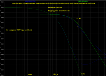
By lowering the ESR (equivalent series resistance) when changing from an electrolytic to a polypropylene, the crossover point and the shape of the roll-off of the filter are significantly changed!
A 50 uF electrolytic might have an ESR of about 2.3 Ohms (just a typical value), at 120 Hz. But I measured the ESR of the 50 uF polypropylene that I bought (Solen) and it is about 0.06 Ohms, at 120 Hz.
The change in capacitor ESR would raise the filter's -3dB cutoff frequency by 7%(!), and would also significantly change the SHAPES of the amplitude and phase of the roll-off of the filter, as seen in the plot that I attached.
I could insert a high-quality resistor in series, ahead of the capacitor, to restore the original crossover plot shapes. But would it then be worth doing it at all, just to have less dielectric absorption? (Or what other improvements might there be?)
It seems that most of the "dramatic improvements" that people have been hearing after they replaced crossover components with higher-quality ones that have the same values MIGHT actually MOSTLY be due to changes they have unwittingly made in the actual crossover characteristics, by using parts with lower DCR and ESR.
My goal is the most-ACCURATE reproduction of the source material.
I definitely do _NOT_ want to base any of my tweaking decisions on my "personal preference", or on subjective listening impressions.
Does anyone think that the accuracy of the reproduction of the sound could be significantly improved, EVEN IF appropriate resistors were inserted in series with the higher-quality coil and capacitor in order to keep the original crossover's amplitude and phase characteristics?
Cheers,
Tom
But then I did a few simulations to compare the old and the new bass circuits, because I was wondering how a lower coil DCR might affect the response of the system. And of course it can significantly raise the power delivered to the speaker, in the low-pass bass filter's pass band. If I lowered the 2.8 mH coil's DCR from 0.36 (measured) to 0.19, it would result in a power increase to the speaker in the bass pass band of 0.7 dB, which would be a 17.5% increase.
I could insert a high-quality resistor in series upstream from the coil to restore the original characteristics. But I'm wondering if it would then be worth doing at all, just to get rid of the possible hysteresis distortion caused by the steel-core coil (satuation of the coil shouldn't be a problem).
Replacing the electrolytic capacitors with polypropylenes turned out to open a much bigger can of worms:
By lowering the ESR (equivalent series resistance) when changing from an electrolytic to a polypropylene, the crossover point and the shape of the roll-off of the filter are significantly changed!
A 50 uF electrolytic might have an ESR of about 2.3 Ohms (just a typical value), at 120 Hz. But I measured the ESR of the 50 uF polypropylene that I bought (Solen) and it is about 0.06 Ohms, at 120 Hz.
The change in capacitor ESR would raise the filter's -3dB cutoff frequency by 7%(!), and would also significantly change the SHAPES of the amplitude and phase of the roll-off of the filter, as seen in the plot that I attached.
I could insert a high-quality resistor in series, ahead of the capacitor, to restore the original crossover plot shapes. But would it then be worth doing it at all, just to have less dielectric absorption? (Or what other improvements might there be?)
It seems that most of the "dramatic improvements" that people have been hearing after they replaced crossover components with higher-quality ones that have the same values MIGHT actually MOSTLY be due to changes they have unwittingly made in the actual crossover characteristics, by using parts with lower DCR and ESR.
My goal is the most-ACCURATE reproduction of the source material.
I definitely do _NOT_ want to base any of my tweaking decisions on my "personal preference", or on subjective listening impressions.
Does anyone think that the accuracy of the reproduction of the sound could be significantly improved, EVEN IF appropriate resistors were inserted in series with the higher-quality coil and capacitor in order to keep the original crossover's amplitude and phase characteristics?
Cheers,
Tom
Attachments
Tom, I don't have a clue but I'm so happy to see somebody actually looking at these issues before diving in that I'm just giddy! I've believed that most of what people hear (if they hear something) when they do mods are the result of not considering ESR and what happens to the resonances it might affect. Here's one more piece of info- you can't duplicate the losses of a high loss capacitor by adding a resistor to a low loss capacitor. The math doesn't work. Well, the math always works, but it tells you that the response differs. Most capacitors maintain more-or-less constant dissipation factor over a wide frequency range. If you convert that (there's a useful utility on my website) to Rs you'll find you need a varying value. Not sure about Rp. That's also a factor in simulations. There are ways to simulate the real performance of a cap, but its a pita and hardly anybody does it.
I could insert a high-quality resistor in series, ahead of the capacitor, to restore the original crossover plot shapes. But would it then be worth doing it at all, just to have less dielectric absorption? (Or what other improvements might there be?)
Tom
resistor in series with paralel caps, definately yes, a must to me
tho I really don't know the theory behind it
resistors in series with paralel inductors, same thing
tho, series resistor on series inductors, I think is a nono
series resistor on series cap is ofcourse ok, and attenuates signal
question is whether the original crossover is optimal
You are replacing a 2.8mH with .36 DCR for one with .19? Why not get an air core with .36 instead of .19. It'll be cheaper and do what you want. Besides this, the 0.7db increase may actually increase the accuracy, depending on the original frequency response. If it was 0.7db too low in this region, then the lower DCR will help.
As for caps, I dunno.
As for caps, I dunno.
actualy you should simuklate the original xover, and design a new one that does have close to same parameters.
You did find out quite cleverly that replacing a component of higher quality in a wellmade xover where the components REAL WORLD properitys where factored will yield in negative results.
You did find out quite cleverly that replacing a component of higher quality in a wellmade xover where the components REAL WORLD properitys where factored will yield in negative results.
Tom, I don't have a clue but I'm so happy to see somebody actually looking at these issues before diving in that I'm just giddy! I've believed that most of what people hear (if they hear something) when they do mods are the result of not considering ESR and what happens to the resonances it might affect. Here's one more piece of info- you can't duplicate the losses of a high loss capacitor by adding a resistor to a low loss capacitor. The math doesn't work. Well, the math always works, but it tells you that the response differs. Most capacitors maintain more-or-less constant dissipation factor over a wide frequency range. If you convert that (there's a useful utility on my website) to Rs you'll find you need a varying value. Not sure about Rp. That's also a factor in simulations. There are ways to simulate the real performance of a cap, but its a pita and hardly anybody does it.
Thanks, Conrad. I have only considered the bass crossover filter, so far, and it seems to work (mathematically) to use a series (ESR-substituting) resistor to restore the original bass crossover characteristics, _IF_ I can assume that the ESR would stay constant over the narrow range of low frequencies, maybe up to about 600 Hz. Beyond that, I would guess the response is so attenuated, either way, that it wouldn't matter.
I actually did a lot of work, a few years ago, to find methods for having good frequency-dependent (and temperature-dependent) spice models of electrolytic capacitors. So I know what you mean about the pita (unless you use capacitors from a company that already supplies the needed spice model parameters).
I still need to find out if better components will be helpful-enough even if their series resistances are maintained or added back in. It seems like I should make the new crossovers as outboard units so that I can leave the original ones in place, and should at least temporarily add switches to enable switching between them. Furthermore, I should add switches to enable switching between having and not having any esr-substituting resistors, wherever they might be needed. I have a very flat measurement microphone that I've never used so it looks like this would be a good time to finally put together a decent computerized measurement system, too.
Cheers,
Tom
It seems like I should make the new crossovers as outboard units...
Tom
I always build any crossover on a piece of wood that sits behind my speakers. It's usually bristling with gator clips and BS so I can mess with it till it sounds right.
It never fails, however that as soon as it's in the box it won't sound right. Luckily, Maggies don't have that problem!
resistor in series with paralel caps, definately yes, a must to me
tho I really don't know the theory behind it
resistors in series with paralel inductors, same thing
tho, series resistor on series inductors, I think is a nono
series resistor on series cap is ofcourse ok, and attenuates signal
question is whether the original crossover is optimal
Tinitus,
Your last point is especially good. I had considered that, too, but didn't mention it above. After I realized that whether or not the original crossover was optimal was what should determine whether or not I should worry so much about changing its characteristics, I decided that unless I could perform good measurements (and knew what I was doing) or had information to the contrary, then, for now, I had to assume that Magnepan knew what they were doing and that their crossover characteristics should be maintained.
Tom
Magnepan knew what they were doing and that their crossover characteristics should be maintained.
Tom
And, they should be. Chances are it's a great crossover...replacing parts will most certainly bring rewards as long as you are careful not to differentiate from parameters too far while experimenting.
DCR is probably something you'll have to pay close attention to if you're changing inductors. A few tenths of a percent are within tolerances of good parts, which you should be able to stay within so long as you're careful to check parts before ordering them.
You are replacing a 2.8mH with .36 DCR for one with .19? Why not get an air core with .36 instead of .19. It'll be cheaper and do what you want. Besides this, the 0.7db increase may actually increase the accuracy, depending on the original frequency response. If it was 0.7db too low in this region, then the lower DCR will help.
As for caps, I dunno.
Yes, I agree, and have been looking at those ready-made air core coils. Or I might wind my own (which I was planning to do for the one with 0.19 Ohms DCR).
I was leaning toward the lowest DCR I could reasonably achieve only because I read so many times that lower DCR was better, and wasn't thinking. But then I asked myself the same question as you have asked here. See my response to Tinitus. It all depends on whether or not the original crossover was "correct" or not.
I could try to FIRST verify (from others' measurements, if I could find some) what the correct resistance in that circuit path should be, and then buy or build an appropriate pair of air core coils. Or I could use a lower DCR air core and experiment with adding different values of series resistance, once I have a good measurement setup developed. Or I could buy or build an air core with the original DCR but then if the DCR needed to be lower I'd have to buy or build another coil.
All of the air core coils I've found for sale are 2.7 mH rather than 2.8 mH. But I did finally find a good source for magnet wire:
cPath_9 | Applied Magnets : Magnet Wire & Magnet Wire Spools - discount wholesale prices.
With one of those 11 lb spools of 12 AWG, I should be able to wind about four coils of 2.8 mH each with 0.19 Ohms DCR. I'll have to do some calculations to see if there is a gauge that would allow me to buy only one spool and still be able to wind two 2.8 mH coils with 0.36 Ohms each _and_ two with DCRs of 0.2 Ohms or less (or maybe whatever turns out to be the optimal DCR).
Tom
You could always try the copper foil air core inductors like Goertz or Erse, I think those have higher DCR than the solid ones like Solen.
Thanks. Yes, I have been looking at them.
Here are the current stock coil and most of the foil air core coil choices that I could find at madisound.com and parts-express.com:
Stock 2.8 mH (nominal), not foil, not air core, 0.36 Ohms (measured) DCR
Alpha Core Goertz 2.7 mH, 14ga foil, air core, 0.370 Ohms DCR, $49.75
ERSE FoilQ 2.70 mH, 12ga foil, air core, 0.365 Ohms DCR, $73.30
ERSE FoilQ 2.70 mH, 14ga foil, air core, 0.441 Ohms DCR, $42.25
ERSE FoilQ 2.70 mH, 16ga foil, air core, 0.669 Ohms DCR, $33.50
Alpha Core Goertz 2.7 mH, 16ga foil, air core, 0.583 Ohms DCR, $36.25
I am leaning toward thinking that foil coils only need to be used for higher frequencies, and also that maybe wire is better for bass coils.
At any rate, I can wind my own, with wire, and get much closer to the mH and DCR that I want, probably for a slightly lower cash outlay, or maybe in some cases slightly higher if I only buy enough wire for two coils.
Tom
actualy you should simuklate the original xover, and design a new one that does have close to same parameters.
You did find out quite cleverly that replacing a component of higher quality in a wellmade xover where the components REAL WORLD properitys where factored will yield in negative results.
Thank you, Arty. For now at least, I agree that I have to believe that Magnepan did take into account the ESR and DCR, and that they correctly set the relative levels of the two outputs.
I suppose that I will have to try to find the ESR specs for the original electrolytic capacitor that was used in each speaker's bass filter, since the ones in my speakers are rather old and their ESRs might have changed by now.
Tom
well if you think about it, if one does not consider the DCR and ESR values in a crossover, matching tweeters is only a blind shot in the dark.
Any respected manufacturer would not commit that.
it would just seem to be not an option. At the least DCR of coils is a must to account.
but anyways, obtaining a more or less suitable mic and doing a simple sinewave sweep could reveal if drivers are not matched properly. An impedance plot can be done too, not that hard.
Then most probably constructing the eqvivalent circuit of the speakers can be done, and you could simulate a new crossover. At worse the original can be used as a reference.
I do not like to findle with exsisting crossovers, as there is no way to tell what was factored when designing them, and even the best intentions can lead to headaches and nothing more. When someone has to design a crossover for a commerical speaker, usualy there is no clue where it will be placed, and used. So if You do mesure the speakers at the place where you would use them, you can get realworld figures and base the design on them. Surely will yield something suited better than a generic approach. As there are factors none of the original design crew could factor regrdless of the effort they put into it.
Arty,
Roger that. Concur.
So if the original crossover design was not flawed, I can probably only mainly hope for three benefits from upgrading components in the bass crossover:
1. Improvement from eliminating possible hysteresis distortion by changing steel core coil to air core (Saturation should not have been a problem.)
2. Improvement from decreasing distortion due to dielectric absorption of capacitor (Anything else?)
3. Increased performance lifespan of polypropylene capacitor with discrete resistor compared to electrolytic with gradually increasing ESR
Is it worth doing?
Tom
well if you think about it, if one does not consider the DCR and ESR values in a crossover, matching tweeters is only a blind shot in the dark.
Any respected manufacturer would not commit that.
it would just seem to be not an option. At the least DCR of coils is a must to account.
but anyways, obtaining a more or less suitable mic and doing a simple sinewave sweep could reveal if drivers are not matched properly. An impedance plot can be done too, not that hard.
Then most probably constructing the eqvivalent circuit of the speakers can be done, and you could simulate a new crossover. At worse the original can be used as a reference.
I do not like to findle with exsisting crossovers, as there is no way to tell what was factored when designing them, and even the best intentions can lead to headaches and nothing more. When someone has to design a crossover for a commerical speaker, usualy there is no clue where it will be placed, and used. So if You do mesure the speakers at the place where you would use them, you can get realworld figures and base the design on them. Surely will yield something suited better than a generic approach. As there are factors none of the original design crew could factor regrdless of the effort they put into it.
If I do get into measuring the response, I would probably try to measure for two scenarios:
1. Outdoors, i.e. with no walls' or ceiling's reflections
2. In my usual indoors listening configuration (whatever THAT is)
If the first one measured as "correct", then I would probably be very hesitant to change anything, unless I could include a switch or adjustment that also allowed returning to the "correct" settings.
I guess the decision to do that or not would depend on the measured and perceived magnitudes of the potential improvement to be had.
We just heard the sound of another can of worms being opened.
Another possibly-big factor would be my own ears' (and brain's) frequency responses, since I am the main listener, by far. So I guess I would need to factor that in, and decide if I need to have a setting that corrects the response.
So maybe I'd need to have at least four settings, including "correct without room effects", "correct FOR ME without room effects", and optionally "correct with room effects", and "correct FOR ME with room effects". Of course, then, the ones "with room effects" would only be correct for a single configuration of speaker locations and listening position. So maybe those would need to be adjustable.
I guess the first thing to try for would be the correct response with no room or listener factors, if the speakers are not already correct that way. Then maybe I could find out what range of adjustments might be needed to be able to cover the other factors, if that seems necessary.
In any case, I do plan to keep the original crossovers in place, so I can go back to them at any time.
Tom
"Correct" is an ill-defined and moving target. I've worked for enough places to know that there is little magic behind the curtain, and that solutions are arrived at by considering a lot of things we might not be thrilled with- preferred suppliers, cost, availability and a certain amount of random dumb luck. Back when those were designed the knowledge base wasn't as good, measurement equipment wasn't as good and there's no reason to suspect the design was somehow close to perfect.
Stuff ages. If you had a time machine and could do a proper DBT on your speakers, vs the same speakers the day they left the factory, I'd bet they sound noticeably different.
In your shoes, I'd certainly take into account the existing design, but I'd also approach it as voicing a completely new speaker and do what pleased me most. Speaking of which, I've always found I tweaked my crossovers differently for vinyl vs CD, so again there's no one answer.
"Correct" is an ill-defined and moving target. I've worked for enough places to know that there is little magic behind the curtain, and that solutions are arrived at by considering a lot of things we might not be thrilled with- preferred suppliers, cost, availability and a certain amount of random dumb luck. Back when those were designed the knowledge base wasn't as good, measurement equipment wasn't as good and there's no reason to suspect the design was somehow close to perfect.
Stuff ages. If you had a time machine and could do a proper DBT on your speakers, vs the same speakers the day they left the factory, I'd bet they sound noticeably different.
In your shoes, I'd certainly take into account the existing design, but I'd also approach it as voicing a completely new speaker and do what pleased me most. Speaking of which, I've always found I tweaked my crossovers differently for vinyl vs CD, so again there's no one answer.
I often do the same thing, I've got all my crossovers out of box where I can get to em. I usually start with a basic design that looks correct mathematically, but if it doesn't sound right, I'll often change values around until it's pleasing.
In this situation, I'd probably remake the original crossover as best I could, but I'd have a pile of parts close by...just in case
")
well outdoors mesurement may not be that usefull at all, since you are not listening them outdoors. I would think if You invest into the project of building new crossovers from the start, then you might as well factor in something the original designer could never. That is the listening enviroment it self.
If You mesure the capacitors used in the current crossover, and compare with the rated value of the caps when they where new, you will see how mutch it can help just to copy the design.
Series resistor to get the original DCR for coils is not a bad or good solution if you ask me. I would rather re-adjust tweeter level according to the new DCR figures.
It would -other than what you allready mentioned- should give you a slightly better overall system efficiency.
So both rebuilding and redesigning can give good results, it is only a mather of what you have time and money for.
Do the original electrolytics have a tolerance? "regular" ones used in power supplies can be +/- 20 percent, and I recall ones decades ago at +80/-20, but perhaps nonpolar electrolytics are better. Regardless, non-electrolytic caps are likely to have closer tolerance, and this will make the crossovers more consistent between channels.Arty,
Roger that. Concur.
So if the original crossover design was not flawed, I can probably only mainly hope for three benefits from upgrading components in the bass crossover:
1. Improvement from eliminating possible hysteresis distortion by changing steel core coil to air core (Saturation should not have been a problem.)
2. Improvement from decreasing distortion due to dielectric absorption of capacitor (Anything else?)
But if you're going this far, I'm thinking you might as well tweak all the crossover components to within 1 or 2 percent. Some components may be orderable with such tight tolerance, otherwise you can buy a few extra and match them. You've got two things you can do, match each component as best you can to its "ideal" value, or find the two that are the closest in value and use one each in each channel.
For this level of tweaking you might also need to measure the sensitivity of the driver for each channel, and if one is significantly more sensitive than the other, add a resistor in series with it.
I suppose you can try it and see, er, hear.Is it worth doing?
Tom
- Status
- This old topic is closed. If you want to reopen this topic, contact a moderator using the "Report Post" button.
- Home
- Loudspeakers
- Multi-Way
- Crossover Component Upgrade Pitfalls?