You should use the lowest that you need, but understand that sometimes you do need more. Maybe they don't sound good past the crossover, maybe they can't handle power outside the crossover, maybe they fail to blend past the crossover.from 6db to 24 db
Your [external] impedance flattening circuitry is interesting. Normally it is not needed. Sometimes it can have an effect. You say you DIY your amp, what do you think? Maybe you can try both, and if you do not notice a difference, then remove it. It is best to wait until you have a crossover that is OK, before you try adding this circuit.
i have an old 5.1 home theater system with tda 7294 for subwoofer and tda 7269 for front and surround , i will try to remodel this system with some quality parts to obtain more quality sound not power , if my system works at 10w but thd less than 1% , for me is enough , i listen many audio systems and in the end i choose less power but high quality sound , so i have some basics in electronics and from some other knowledge acquired in time i decide to build everything i can by me , i will make an 12db crossover according to schematic posted and see what result are. One thing i use as streamer an Rpi 3 with DAC board , Moode software , till now , everything works fine , but sound quality still
not what i want , i use some old speaker .
.
not what i want , i use some old speaker
.
There is a slice missing at the bottom of the lower image but phase tracking looks the same on both as far as I can see.
Yes its just the inverted connection for both the drivers, wanted to see which one will be better
I dont know if this already common knowledge around here but I realised there is very easy way to design/test/experiment with 2-way active/passive/PLL XOs using parametric EQ in Jriver DSP without needing any multichannel equipment (which if you own you were probably already be interested in a digital XO).
You can use the mixer to copy one channel to other for a mono output and then design the crossover within the left and right channels connected to the HF and LF driver of a single speaker.
You can use the mixer to copy one channel to other for a mono output and then design the crossover within the left and right channels connected to the HF and LF driver of a single speaker.
Attachments
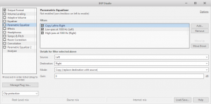
Thanks for sharing this. This method lends itself well to the tweaking style of the no measurement crossover. For the final step you need to translate what you have (your wanted response adjustments) back into a filter which you can work with.
You mention the opportunity of having a multiple channel system. I have used multiple amplifiers because they can help with the process of setting up multiple subwoofers, which help with room modes, because the responses of these need to be different to the main speakers.
I also use multiple amps because I like building them and trying combinations on the different drivers, and I've done this even when there was no need to do so. However it makes it easy to try capacitors before the amps, or capacitors and inductors after the amps, or either active filters or digital line level filters.. and of course, combinations.
Whichever type you use, you can still achieve the same, wanted response. I'd need a reason to choose a preference, so whatever I have can serve me well. Whichever kind you choose to work with, the 'without measurement' goals will be the same.
Hi frangus. I'd add a couple of things in that case. The first is about finding the right crossover point. The second is about dealing with the tweeter impedance.
For a LeCleach horn, a couple of things.. it is typically better used above and not too close to its cutoff frequency... and it has a continuously varying directivity. Somewhere in there you'll find a directivity to match with a woofer. It will likely be around 90 degrees. This means the size of the woofer has to be chosen to match the cutoff frequency of the horn. hornresp.exe is good at predicting things here.
The impedance of a compression driver on a horn can be less simple than a dome tweeter. It can be sharper, higher and not a simple single bump. You can use the techniques shown in the tutorial but there will be more room for improvement in being more specific when fixing the impedance. With the right amount of work it should be possible to do it near perfectly.
Hi Allen, its been a while. Thank you for your response. You have inspired me to go back over the notes for basic crossover design. I have xsim, mic and DATS V2 so I think I will do it the more precise way. Cheers
Also Allen, I'm guessing you are retired or young or both to take on such a volume of questions plus moderating and general discussion? Are you an ex-engineer or a self-taught fanatic young engineering early-retiree? Or are you running a mega corporation and you do this in your spare time, which would be all the time, because you have good managers that do all the work for you so you can do something even more fun whenever you want?
Last edited:
Well, I don't need to make it easy for them to assassinate me , but suffice it to say I'm not ready for retirement yet... I'm both actually, I became interested in electronics at the age of 4, and later I went to big peoples school and made it official. My related childhood interests, apart from what you can do with switches, was speakers and valves. I knew that one day I would understand them.
, but suffice it to say I'm not ready for retirement yet... I'm both actually, I became interested in electronics at the age of 4, and later I went to big peoples school and made it official. My related childhood interests, apart from what you can do with switches, was speakers and valves. I knew that one day I would understand them.Audax tweeter for easy construction without measurements
I really like to use in loudspeaker projects Tweeters which can be found in cars and are produced in thousands for the industry.
The copy of the classical Audax Tweeter - a mix of dome and cone which functions very fine with just one capacitor and nothing else.
You can see the combination of a fullrange driver with 0,75mh induction of the voice coil and natural decline beyond 4khz in combination with this type of Audax Tweeters in this project:
The Advantages of Floor Coupled Up-Firing Speakers
I optimized impedance of the tweeter array and the capacitor (foil type) only by listening as this sort of in - room optimized loudspeaker with surround sounding qualities are far from easy to measure.
In this case listening is more important than measuring!
Attachments
Last edited:
When you trade off slope and frequency, there comes a point where it becomes clear there is a limit to what you can do.
When you are crossing this way you rely on hearing when the tweeter is being pushed too far. You want to hear the mechanical limits and hope, as is often the case, that this comes before reaching the electrical limits. To be honest it is rare that I damage tweeters but I also do not play them where they are distorting. You need to take more care when you are doing something unusual like you have suggested here.
When testing keep in mind that broadly speaking, playing drivers close to their limit for some time can build up heat. Similar to the process of soldering... within reason you can go a little hotter if only for a short time.
Hello Wik,
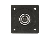
If you want to make a complicated filter - no problem, I could measure everything. I recommended this Audax type tweeter (see foto) because it really works well with just one capacitor. It is built for that. So it is much easier to build with these tweeters a loudspeaker without measurement capabilities.
I really appreciate the sound of these tweeters if used with a foil type capacitor.
Hello Allen B,
you are quite right in stating that a 6db filter can damage a tweeter if there are too many watt input.
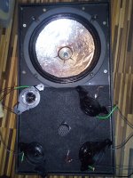
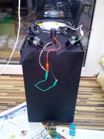
This audax alike tweeter has ferrofluid which helps a lot to get some more headroom when driving the speaker hard. If you use multiple tweeters like in this example of a Sonab loudspeaker copy then the tweeters can take more wattage.
If you want to make a complicated filter - no problem, I could measure everything. I recommended this Audax type tweeter (see foto) because it really works well with just one capacitor. It is built for that. So it is much easier to build with these tweeters a loudspeaker without measurement capabilities.
I really appreciate the sound of these tweeters if used with a foil type capacitor.
Hello Allen B,
you are quite right in stating that a 6db filter can damage a tweeter if there are too many watt input.
This audax alike tweeter has ferrofluid which helps a lot to get some more headroom when driving the speaker hard. If you use multiple tweeters like in this example of a Sonab loudspeaker copy then the tweeters can take more wattage.
Attachments
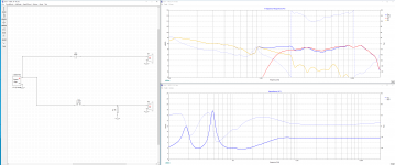
This is my first attempt at designing a crossover - I am using XSim, and I measured the impedance / phase with my DATS v3, and the response sweeps were done using REW. The woofer was installed in the mass loaded transmission line cabinet, and the tweeter is a Linaeum ET-8 dipole mounted on the top of the cabinet (tweeter made by Radio Shack).
Here's my crossover design, and the predicted response.
I am wondering if the dip centered at ~800Hz is a resonance of the woofer? There is a small impedance ripple at that frequency. Maybe this will get better with some more use of the speaker? I will keep using them, and remeasure them later to see if this changes anything.
I am playing them initially with an active crossover (miniDSP 2x4 HD). With that unit, I have set the crossover to be 2nd order, at 1100Hz for the woofer and 1200 for the tweeter - but the tweeter's response naturally rolls off starting at about 1600 or so, I see now with the measurements.
It sounds very good with the active crossover. I am also surprised at how much higher the woofer keeps responding - and it seems to be out of phase above 2kHz. How would I add a steeper slope up at 2kHz to try to reduce the woofer's output up there?
Edit: in the active crossover, I am lowering the tweeter output by 3.5dB, so I am surprised that I don't seem to need to do this with the analog crossover? Maybe my response measurements where not done correctly? I had the mic at the same distance from each driver, and obviously I kept the volume the same. I did move the mic vertically to be in the center of each driver - maybe I need to pick one position a bit farther away, and measure both at the same point?
Attachments
Last edited:
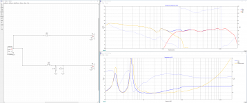
Some further trial and error nets me a small positive change, I think? Made the woofer a 2nd order (kinda' obvious?) and got rid of most of the upper end of the woofer.
I am still concerned about the tweeter's rise starting at ~5kHz. Maybe I can do something for this - I did try a few things already? I will be trying this out on the outside of the cabinet (it has two pairs of binding posts) so maybe it can be changed later?
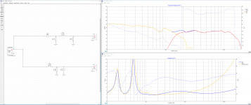
And I have a third version, that makes the tweeter also 2nd order. I want a "house curve" but this may be a bit more of the shelf down than I need?
I am still concerned about the tweeter's rise starting at ~5kHz. Maybe I can do something for this - I did try a few things already? I will be trying this out on the outside of the cabinet (it has two pairs of binding posts) so maybe it can be changed later?
And I have a third version, that makes the tweeter also 2nd order. I want a "house curve" but this may be a bit more of the shelf down than I need?
Attachments
- Home
- Loudspeakers
- Multi-Way
- Introduction to designing crossovers without measurement