The title states "without measurement".
Judging by the number of graphical plots in the first few posts, it seems that measurement is critical to determining some, or many, of the component values.
Judging by the number of graphical plots in the first few posts, it seems that measurement is critical to determining some, or many, of the component values.
seems to reinforce my conclusion.Furthermore, without phase and delay information available, chasing higher orders can be relatively ineffective.
The drop off is happening with the tweeter not the bass/mid. If I move my head slightly left and right up or down from the normal listening position I lose a considerable amount of treble.There are a couple of common reasons that the top end might sound rough or fatiguing. Since you seem to prefer the woofer to play higher in frequency, I'd assume it's due to the off axis sound up high. This can come down to personal preference but I prefer less.
As a woofer goes higher in frequency, it produces less off axis sound. Just to illustrate, imagine taking a small stone and dropping it into a pond. Note the width of the ripples. Now take some sand and drop it over that wider area. The ripples will have trouble forming as the parts do not add properly and they partially cancel one another. Woofers will lose most of this energy off to the sides, more with increasing frequency.
Having been in this situation I understand the temptation to try and run the better driver as wide in frequency as possible to get the best out of it. What you end up with in this case will be reflections that are more loud above the crossover frequency than below due to the tweeter and its wider radiation.
When you listen to speakers in a room, you can expect the lower frequencies to be coming from all around, and you can make a choice to taper this off so that the higher frequencies are mostly coming to you directly. What you want to avoid is reducing the off-axis sound at some frequency and allowing it to be present again at higher frequencies, which is what you have when you cross a woofer quite high to a dome tweeter.
It could be worth exploring some different types of speaker, and there are two common alternatives that can achieve this end. One of them is to use a larger driver for the treble. An example would be using a small full range driver. The advantages of this are that the treble will be more direct (meaning less reflected sound) and therefore more relaxed even when designed for the same level on your listening axis as a dome. You'll also be able to cross lower in the midrange (good), and you'll be able to use a larger woofer. This format has come to be known here as a F.A.S.T.
The other is to use a horn to control the dispersion in the treble. A waveguide is a kind of horn that has been designed primarily for controlling the directivity. It is usually conical or similar. If you know the woofer and the waveguide angle you want to use, you find the frequency where the woofer radiation narrows to that amount and make sure the waveguide and tweeter can be crossed that low.
Sorry if I didnt explain myself properly. The speakers did not have this problem when there was the original tweeters in the speaker (which blew) that was using a first order x-over.
OK, there are a few more possibilities but firstly are you familiar with standing waves? I first recall noticing this as I was doing some measurements on a tweeter. I had a tone of maybe 3kHz playing and I was walking around the room trying to find my pencil. The sound would cut in and out as I moved and it seemed to be laid out on a grid of a few inches per square. This is an interaction of room reflections. It can happen as the result of a single reflection, or even dissimilar distance between speakers although it is easier to notice when you play a steady tone like I was.
A loss in treble is a broad statement which could mean any of the kHz range and it is sometimes difficult to tell which driver is actually responsible just by listening.
You say that this happens when you move vertically or horizontally. If it were the tweeter interacting out of phase with the woofer then it would happen vertically, as you move closer/further from each driver, but not horizontally. It is possible that you have more than one outstanding issue but I'll deal with the possibilities separately.
Another concern is the fact that you use the P17 up to 4kHz. This sized driver is beginning to lose its off axis energy down at 2kHz or so. It's normally not too much of a problem to cross there as the tweeter's energy below its crossover may be enough to fill the holes. In your case the odds are stacked against you so to speak...firstly the 17 will have fair losses to the sides by 4kHz. Secondly the tweeter would have to reach more than an octave below its crossover still having enough energy which thirdly, it might have if you were using a first order crossover but you aren't, (Obviously doing so would have its good and bad points).
Try moving your ears horizontally so that the problem happens, and move further to the side and see if the treble returns. This might indicate that you have a reflection/standing wave issue (try this as well with only one speaker playing). Also try using a second order filter on the tweeter. If this helps it could indicate one of three things either the 2-4kHz region needed filling, or the third order filter was producing a lumpy response (as these can be more difficult to get smooth using standard formulas on a real driver), or that you have crossover phasing issues. If this last one is the case, then simply flipping the polarity of the tweeter will change the locations where you can hear the treble going in and out.
Last edited:
OK, there are a few more possibilities but firstly are you familiar with standing waves? I first recall noticing this as I was doing some measurements on a tweeter. I had a tone of maybe 3kHz playing and I was walking around the room trying to find my pencil. The sound would cut in and out as I moved and it seemed to be laid out on a grid of a few inches per square. This is an interaction of room reflections. It can happen as the result of a single reflection, or even dissimilar distance between speakers although it is easier to notice when you play a steady tone like I was.
A loss in treble is a broad statement which could mean any of the kHz range and it is sometimes difficult to tell which driver is actually responsible just by listening.
You say that this happens when you move vertically or horizontally. If it were the tweeter interacting out of phase with the woofer then it would happen vertically, as you move closer/further from each driver, but not horizontally. It is possible that you have more than one outstanding issue but I'll deal with the possibilities separately.
Another concern is the fact that you use the P17 up to 4kHz. This sized driver is beginning to lose its off axis energy down at 2kHz or so. It's normally not too much of a problem to cross there as the tweeter's energy below its crossover may be enough to fill the holes. In your case the odds are stacked against you so to speak...firstly the 17 will have fair losses to the sides by 4kHz. Secondly the tweeter would have to reach more than an octave below its crossover still having enough energy which thirdly, it might have if you were using a first order crossover but you aren't, (Obviously doing so would have its good and bad points).
Try moving your ears horizontally so that the problem happens, and move further to the side and see if the treble returns. This might indicate that you have a reflection/standing wave issue (try this as well with only one speaker playing). Also try using a second order filter on the tweeter. If this helps it could indicate one of three things either the 2-4kHz region needed filling, or the third order filter was producing a lumpy response (as these can be more difficult to get smooth using standard formulas on a real driver), or that you have crossover phasing issues. If this last one is the case, then simply flipping the polarity of the tweeter will change the locations where you can hear the treble going in and out.
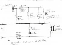
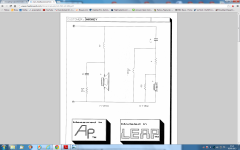
OK Thanks, I'm going to try a 2nd order linkwitz-riley again and drop the
x-over to 2400Hz with polarity reversed on the tweeter. I did try this a few weeks ago but the top end was a bit splashy for me so maybe I need a notch filter in there also. Tried it with Pink and white noise and there was definitely an audible rise at the top and it didn't blend well.
This was the circuit I used for 2nd order a few weeks ago.
Attachments
It's worth a try, and at the least will give you the chance to cross some possibilities off the list. Don't lock yourself in to one polarity, there are a number of factors that will detract from what the texts will say, as true as they might be in an ideal world.
The treble region is very difficult to get just right, even when great lengths are taken. You should be aware of the following things.... Small problems here will sound like large problems. Most speakers seem to be set with the treble too high for reality and when people such as ourselves try to build a speaker we may find it hard to trade realism for what we are used to. Also you shouldn't assume that a dome tweeter is what you're looking for, although it may be. They have a specific nature about them (dispersion pattern, and the way in which they produce distortions), but they have advantages as well. I stopped using them some time ago.
The treble region is very difficult to get just right, even when great lengths are taken. You should be aware of the following things.... Small problems here will sound like large problems. Most speakers seem to be set with the treble too high for reality and when people such as ourselves try to build a speaker we may find it hard to trade realism for what we are used to. Also you shouldn't assume that a dome tweeter is what you're looking for, although it may be. They have a specific nature about them (dispersion pattern, and the way in which they produce distortions), but they have advantages as well. I stopped using them some time ago.
Yes it is the treble region I'm having the most difficulty with, I am Confident the bass/mid seems right now but I am trying to get the tweeter to blend in and not stand out. I want it to be natural sounding, and yes I have fallen into the trap of having too much treble before and leaned from that. I always swap the polarity on the tweeter between every new configuration test so as not to miss anything.
AllenB, your posts #116 and #117,
To a certain extent I agree with you. The acoustic response can be a great deal different from the applied voltage versus frequency.
If a first order cross-over network is constructed with electrolytic capacitors, and off-the-shelf inductors that are of a value that is only as close as possible to the calculated value, then yes, there is no point in quibbling about a few Ohms of difference between nominal and what the impedance actually is.
But if the order is 2nd or higher and capacitors with tolerance of 5% or even 1% are used, and the values of the inductors are within a few percent of the calculated values, then I think the designer would also want to base the values of inductance and capacitance on a load impedance that is at least a good deal closer to the actual impedance than nominal.
In the above situation where greater accuracy is sought for, and perhaps would result in improvement from the start, why would anyone say, "Well, I know that the impedance of this driver is about 1,2 times Re at the crossover frequency, but I'm going to base my values of capacitance and inductance on the nominal impedance"?
Regards,
Pete
Last edited:
I always swap the polarity on the tweeter between every new configuration test so as not to miss anything.
What do you mean here, do you design the speaker by ears or by software? (Software will tell you sufficient information)
Yes it is the treble region I'm having the most difficulty with
Is that acoustically 2nd order too? (It looks so to me). Acoustically LR2 is difficult. First issue is to get the overlapping phase at Fx is not always possible with normal measures. When you get it right (the phase, the response) the sound may still not right, especially at high spl where the slope may not be steep enough to avoid the driver resonance (Fs).
I don't recognize the tweeter, but the values are a bit strange to me. For the woofer, 0.9mH/4u7/5R6 is relatively very high, but for the tweeter 6u8/0.6mH is relatively low. Are you sure there is no extra dB at midrange frequency?
From my experience, no tweeter will sound good with 6u8/0.6. This of course depends on the tweeter parameters, what I mean here is from tweeters that I have ever used. Honestly, by intuition I think the crossover won't work, but you know better.
mart.s, sorry I just read your previous posts regarding your crossover. I think you should post the original crossover before the original tweeter blew.
If you're familiar with designing speaker with these FRD/ZMA files, even without measuring the new drivers, you can still do it using similar drivers. Yes, there is little effort to find this similar drivers, but doable.
So the original is at 4kHz? And you don't have issues with breakup? Then there is no problem with the woofer. We don't need additional filter and we can cross the woofer anywhere we want.
Now the original tweeter. First order you said? I think we can forget the tweeter. Your crossover posted above definitely is too low.
But you still can show the original crossover at 4kHz, to understand the "properties" of the woofer. It is also difficult if both woofer and tweeter has different impedance (e.g 4R versus 8R). What is the impedance of this Audax tweeter?
I think it's more to do with how different the response can be by using any single value for the impedance rather than the full plot, and the fact that tweaking is to be expected when measurements are not taken. I set up an example of this with a simple crossover changing only the impedance.then I think the designer would also want to base the values of inductance and capacitance on a load impedance that is at least a good deal closer to the actual impedance than nominal.
The tweeter (green) has the crossover applied (blue) for the target (black).
The pink trace shows the effect of using the full impedance plot after the phase has been set to zero. Zero degrees has no significant meaning in this case, it could be set to anything but it gives a clue toward the benefit of including it, as usually when it is left out it is left at zero.
The yellow and cyan traces show the result of setting the impedance to equal an eight ohm resistance, and a twelve ohm resistance. The peaking is because this crossover was designed for the true impedance, rather than a compensated one but this is of course irrelevant. It is the difference from the target that I'm trying to show.
The more thoroughly you can compensate the impedance, the less significant all this becomes but at some point this too is going to need measurement, and once these initial measurements are done there is no longer a need to choose a value for the impedance.
Attachments
Last edited:
AllenB, thanks for the feedback.
This concerns designing crossovers without measurement. So if the cross-over frequency is in the rated impedance region of a driver, it is just plain sensible to calculate the values of capacitance and inductance based on rated rather than nominal impedance. In practice, it might not make a big difference in terms of the acoustic response. But using rated instead of nominal would be logical.
A difficulty I suppose is that most often the crossover frequency cannot practically be in the rated impedance region of both of the involved drivers.
Regards,
Pete
The more thoroughly you can compensate the impedance, the less significant all this becomes but at some point this too is going to need measurement, and once these initial measurements are done there is no longer a need to choose a value for the impedance.
A difficulty I suppose is that most often the crossover frequency cannot practically be in the rated impedance region of both of the involved drivers.
I'm a little bit confused regarding how you put the impedance plot (e.g. ZMA file) into the perspective of your discussion.
I haven't read/followed this thread. I was familiar with the FRD Consortium tools and method so I didn't find a need to read the thread when it was posted in 2011. But I think there may be interesting discussion so I will read the thread from the beginning now.
I went and had another think about how to show the differences in a way that would help others decide how significant this can be. The behaviour of a second order electrical filter tends toward being correct at both frequency extremes regardless of the impedance, while being more sensitive to it in the middle. A lower Q filter (such as the Linkwitz-Riley (Q=0.5) that we often start with) will tend to be more sensitive over a wider region.
I modelled an impedance that is resistive at 12 ohms below 1kHz, and 8 ohms above that. I set a target L-R rolloff at 1kHz, and also in half octave steps for two octaves either side of 1kHz. I then used calculated values of filter for each of these using 8 ohms (blue curves) and 12 ohms (red).
This way, one could look at the driver impedance curve and roughly estimate how much the response could be affected by how far away from the crossover point the impedance peak is.
Attachments
Last edited:
Ok - a little forbearance if this is posted in the wrong place.
First Issue:
I have a pair of $1 drivers from my first project that are rated on the back at 4Ω apiece.
They measure at:
Tweeter measures at 6.1Ω
Mid/bass measures at 5.4Ω
Their crossover was a 4.7uF capacitor wired to the mid/bass in series with the tweeter.
A First Order Butterworth, but without an inductor?
So what would this be called and how calculated?
Using several sources for the calc of a first order I used these values:
High Pass Impedance: 6.1Ω
Low Pass Impedance: 5.4Ω
xo Frequency Hz 5546 hz
To reverse engineer a capacitor value of 4.699uF
1) Have I performed these calculations correctly?
2) Have I assumed the correct layout of the xo as a first order has coil value and this xo had just a capacitor?
5546 seems very high even for the low price boxes this first project came from.
=============================
Second Issue:
I have purchased an AS-23 xo by Kasun, 3200hz pt, 150W rated, 3rd order with a Zobel.
I want to reverse good specs for two drivers to place into this xo in a bookshelf box (the same from the drivers above) and not mess with it anymore and move on to the next project. A 1" or 1.5" tweeter and a 3" mid/bass. The box is confining driver size choice and the xo will confine the specs.
What specs am I looking for and what calculators/software should I be using?
I realize this is backwards, but I am not up to designing an xo at this stage, nor building a box, and simply wish to pair this xo with some compatible drivers based up T-S and other specs, and finish this project and move on to the next one.
I don't want to just toss in two good drivers without being thoughtful and having intent with this first project.
Currently the drivers in it are $3 replacements I bought just to get basic project skills up to speed. Now that proof of concept is at hand, I want to put some better drivers ($30 apiece) in and finish this.
Many thanks in advance!
Last edited:
Ok - a little forbearance if this is posted in the wrong place.
First Issue:
I have a pair of $1 drivers from my first project that are rated on the back at 4Ω apiece.
They measure at:
Tweeter measures at 6.1Ω
Mid/bass measures at 5.4Ω
Their crossover was a 4.7uF capacitor wired to the mid/bass in series with the tweeter.
A First Order Butterworth, but without an inductor?
So what would this be called and how calculated?
Using several sources for the calc of a first order I used these values:
High Pass Impedance: 6.1Ω
Low Pass Impedance: 5.4Ω
xo Frequency Hz 5546 hz
To reverse engineer a capacitor value of 4.699uF
1) Have I performed these calculations correctly?
2) Have I assumed the correct layout of the xo as a first order has coil value and this xo had just a capacitor?
5546 seems very high even for the low price boxes this first project came from.
1) Yes, but some might object to you calculating the cross-over frequency based on the DC resistance of the tweeter. The impedance of the tweeter is always at least 1.2 times the DC resistance. I'm assuming that you got the values of impedance (actually direct current resistance) by measuring with an ohmmeter, but I could be wrong.
2) The cross-over is a high-pass filter for the tweeter only. There is no filter on the mid-range. The design relies on the natural roll-off of the mid-range.
A cut-off frequency of the tweeter at 5 kHz is not unusually high. If the size of the mid-range is fairly small, a cross-over at 5 kHz is fine.
Regards,
Pete
Last edited:
Ok - a little forbearance if this is posted in the wrong place.
First Issue:
I have a pair of $1 drivers from my first project that are rated on the back at 4Ω apiece.
They measure at:
Tweeter measures at 6.1Ω
Mid/bass measures at 5.4Ω
Their crossover was a 4.7uF capacitor wired to the mid/bass in series with the tweeter.
A First Order Butterworth, but without an inductor?
So what would this be called and how calculated?
Using several sources for the calc of a first order I used these values:
High Pass Impedance: 6.1Ω
Low Pass Impedance: 5.4Ω
xo Frequency Hz 5546 hz
To reverse engineer a capacitor value of 4.699uF
1) Have I performed these calculations correctly?
2) Have I assumed the correct layout of the xo as a first order has coil value and this xo had just a capacitor?
5546 seems very high even for the low price boxes this first project came from.
=============================
Second Issue:
I have purchased an AS-23 xo by Kasun, 3200hz pt, 150W rated, 3rd order with a Zobel.
I want to reverse good specs for two drivers to place into this xo in a bookshelf box (the same from the drivers above) and not mess with it anymore and move on to the next project. A 1" or 1.5" tweeter and a 3" mid/bass. The box is confining driver size choice and the xo will confine the specs.
What specs am I looking for and what calculators/software should I be using?
I realize this is backwards, but I am not up to designing an xo at this stage, nor building a box, and simply wish to pair this xo with some compatible drivers based up T-S and other specs, and finish this project and move on to the next one.
I don't want to just toss in two good drivers without being thoughtful and having intent with this first project.
Currently the drivers in it are $3 replacements I bought just to get basic project skills up to speed. Now that proof of concept is at hand, I want to put some better drivers ($30 apiece) in and finish this.
Many thanks in advance!
Your calculations seem correct, and although quite crude, designs like this are still used today (I believe Epos still do this) When the drivers are well matched you can get away with very minimal X-Over like a first order, even without a Woofer inductor. 5000Hz and above X-Over is Ok with smaller woofers under 5 inches as most 4-5" woofers roll off at about 3500 - 5000Hz.
Personally Unless the drivers are especially well matched I have not had much success with first order X-Overs, Tweeters will usually need a low Fs (resonant frequency) of about 550Hz for low order X0's Tweeters over 1000Fs usually need at least a second order and preferably a third order which means a lot more expensive components. Quality tweeters from the likes of SEAS and Scanspeak with low Fs are expensive but you can then use a first or second order X-over with less parts, unfortunately you cant normally have it both ways. The problems I had with first order XO's was getting the teeters to blend in properly and not sound aggressive, I've played around for months trying to get it to sound RIGHT by ear as I don't have all the measuring equipment like most beginners. I have always reverted to 2nd order LWR or third order butterworth.
The other problem is driver impedance's are always changing when being driven by a signal (and many other reasons) so a lot of the standard formulas go out of the window and it becomes a bit of trial and error using the standard calculators just as a starting point.
With the drivers you already have I would just stick to the original design and buy some small (And preferably) pre-cut (non ported) cabinets for them and get a decent 4.7uF mkp cap and a bit of cheap foam damping to line them with and away you go.
As far as your second issue goes that would be totally the wrong way to approach it unless you are willing to basically rip the AS-23 to pieces time and time again and change values etc to get it to work with drivers you dont even have yet. You must start with the drivers and then design the X-Overs to match the specs of the drivers. Of course there is an easier way to get what you want and that is to scour the net to find all the projects using those AS-23's and see what drivers they are all using and the different mods to the X-Overs.
Unfortunately speaker design is a complicated and time consuming affair, especially if you want perfection from a limited budget.
If you are prepared to spend a bit of cash then I would look at drivers from the SEAS Prestige range or Vifa. Madisound.com and parts-express.com are good places to start.
Have a look at the Peerless 830855 SDS 4" Woofer and Vifa D27TG35-06 tweeter which are in your suggested price range. -Have fun
")
Sorry chaps I hadn't realized you had replied to my post regarding 2nd order crossover.
The original crossover values were not known, But originally I believe it used a Seas 27TBFC/GH1212 tweeter. The x-over consisted of an ferrite core inductor for the bass driver and a 5uF cap with a 5 ohm resistor for the tweeter. The nearest x-over I could come up with that matched these parts was a first order Solen split crossed somewhere around 3000Hz with the woofer inductor about 0.6mH.
I reduced the capacitor value in the new 2nd order to 5uF and it sounds about right now with the Audax tweeter.
The new 2nd order was based on the following circuit from madisound (based on the closest match to my drivers) with a few slightly different values, And yes I have done it all by ear with no measuring tools or software, just a friend's Proac Studio 100's as reference.
I am STILL getting a little sibilance on the tweeter which I guess is due to a rise at the tweeter crossover point and I just cant be bothered to mess around with notch filters or re designing the x-over to a 3rd order which I know would help. I am lucky that the Audax tweeter I have is buttery smooth which helps somewhat. I also tried a SEAS 25tdfc a while back which I didn't like the sound of so sold on for peanuts and went back to the Audax.
Madisound x-over below:
Attachments
No, but probably close.A First Order Butterworth, but without an inductor?
Firstly, you will only create a first order butterworth filter with a capacitor or an inductor if the impedance is flat (and impedance phase is zero), meaning it is behaving like a resistor. Otherwise such a Butterworth filter would require more components (which in this thread has been addressed in the form of impedance compensation).
Secondly, the choice of filter depends on the response of the driver. In other words getting the driver response to resemble a Butterworth slope might require a completely different electrical filter. For example: using only a capacitor on a tweeter above the resonance causes the response to not roll off so readily. It will come back up near the resonance due to the impedance peak. Combined with the driver's own rolloff, the response may resemble the slope of a higher order filter at a lower frequency.
Take a look at the impedance plot for a driver similar to yours. It will vary, sometimes higher than the nominal value (ie: 4 or 8 ohms) and in some places maybe lower. A starting point is to use a value of impedance that you feel best represents the region near the crossover point on the plot. If you don't have a plot then perhaps you can just use a slightly smaller capacitor than you calculate.Using several sources for the calc of a first order I used these values:
High Pass Impedance: 6.1Ω
Low Pass Impedance: 5.4Ω
This is a common approach when cost is a major factor. A woofer will be chosen that can play without a crossover and still sound half OK, then a small tweeter is chosen to fill in the top end. This method has several things wrong with it as you can see.5546 seems very high even for the low price boxes this first project came from.
Specs are probably not what you are looking for, but rather two drivers with a similar response. This may possibly mean that the new drivers will sound similar to the originals.I want to reverse good specs for two drivers to place into this xo
Now, I suppose that if your tweeter has a lumpy response then finding a new one without the peaks could make an improvement because a simple crossover does nothing to the middle and upper treble (but a good crossover would). If you found such a tweeter it would need a similar response and impedance if you do not want to change the crossover (ie it might have a similar resonance and rated impedance). You'll also need to match the sensitivity unless you are going to change the woofer as well.
If it works now, it may or may not work with new drivers unless you are prepared to make adjustments. Perhaps you can practice with the drivers you have now? They may sound good with a better crossover.
I think I can see what you're saying here, but I'd just like to clarify that matching drivers in general may not always be about things that are obvious at first glance. While some would, my own speakers wouldn't sound right with such a simple crossover and I wouldn't say my drivers were not well matched.When the drivers are well matched you can get away with very minimal X-Over like a first order, even without a Woofer inductor.
Such a change would be incidental. For all intents and purposes you can consider that the impedance remains what it is when measured if the operating conditions aren't changed.driver impedance's are always changing when being driven by a signal
CongratulationsThe new 2nd order was based on the following circuit from madisound (based on the closest match to my drivers) with a few slightly different values, And yes I have done it all by ear with no measuring tools or software, just a friend's Proac Studio 100's as reference.
I am STILL getting a little sibilance on the tweeter which I guess is due to a rise at the tweeter crossover point and I just cant be bothered to mess around with notch filters or re designing the x-over to a 3rd order which I know would help.
Some may not be convinced that tweaking by ear can produce a good result. Don't get me wrong, there is a point where a plethora of measurement and calculation along with various sensible acoustic choices becomes the only way through, but even the knowledge of this can go a long way. I still tweak by ear in between other things (even when it's only to compensate for a bad recording).
Thanks for the replies!
I tried the old drivers with the new xo first thing and they sounded terrible. Both tweeters had clearly seen over-loaded output from a low wattage SS amp and they were cooked above 9k.
The two replacement drivers I put into the boxes with the Kasun sounded ok until I pop tested for polarity and now I want to replace them. The originals and replacements are of such low grade that specs beyond ohms are not to be had and measurements are beyond my scope at this point.
I am going to get some drivers that would seem to work well with the natural roll offs, impedance peaks and a 3200 xo point and consider this first project as complete. It has fulfilled the goals of trouble shooting, systems processes, solder skills and basic novice procedure t/s. It does not sound bad at all, no sound-stage though. I will find some wooden boxes for the outboard xo's and move on.
- Home
- Loudspeakers
- Multi-Way
- Introduction to designing crossovers without measurement