reconsidering my speaker project based on the knowledge i gained from :
http://www.diyaudio.com/forums/multi-way/183853-attenuation-problem.html
-> thank Your for the help, and feedback again<-
I will not be able to post all the details in a single post, as its a work in progress. Still, i have done some homework and i would like to share it.
So let us see what i got sofar worked out.
The midbass unit drivers specification is :
Rdc : 7.3 Ohm
B*L : 7.317 Tm
Sd : 132 cm^2
Cms : 0.756 mm/N
Mms : 16.925 g
Rms : 1.447 Kg/s
Fs : 44 Hz
Vas : 18.7 L
Qms : 3.280
Qes : 0.645
Qts : 0.539
Xmax (linear) : +- 4.2 mm
Xmax (Mechanical) :+- 6 mm
Spl : 86 dBL (1 watt, 1 meter)
Powerhandling : 55 VA (IEC-268-5)
Diameter (outer, includes basket) : 174 mm
Nice little midbass.
The tweeter specfication is :
Rdc : 3.2 Ohm
B*L : 2.18 Tm
Sd : 8.6 cm^2
Cms : 0.1128 mm/N
Mms : 0.3 g
Rms :0.22357 Kg/s
Fs : 825 Hz
Vas : 0.01 L
Qms :7.108
Qes :1.07
Qts : 0.93
Spl : 90 dBL (1 watt, 1 meter)
Very nice tweeter, choosen for its very low FS, and good documentation.
The target is still to make some better speakers for my little TDA1557Q amp.
The box should be around nett. 55-60 Liter, and tuning should be at close to 37 Hz.
The drivers share the same volume.
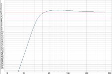
The picture named midbassj.jpg shows the estimated responce of the 2 paralell connected midbass drivers.
The choice of crossover point was selected simply by multiplying the tweeters Fs by 3. I read that with a 2nd order filter i should be just fine with this methood.
-> comments welcome here<-
For a crossover network to work as intended, both midbass and tweeter units need impedance correction networks.
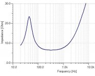
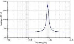
The next 2 pictures show the midbass and the tweeter impedance simulated, in this order. (compared to datasheet, the simulation seems quite accurate.)
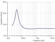
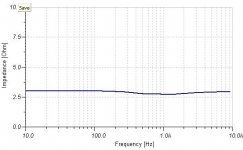
The next picture shows the simulated impedance for the drivers with the correct impedance correction networks added.
Now i can read the graph to see what impedance value does the drivers have around the crossover point, and i can design the crossover
The tweeter has 2.83 Ohm impedance at crossover point,
the midbass unit has 6.48 Ohm impedance.
Quite different from 8 and 4 Ohms
Have to admit it, first time i try to design anything with these -for me- new tools, lots of fun.
There is only but 1 tiny problem with simulations.
In real life there is no way i could get an exactly 15.4 uF capacitor for the midbass compensation circuit, as an example.
So, what i did, is look up the components for the network, and simply use the real values, simulate the worse and best case, and avarge it out to see how mutch difference will it make.
Example, capacitors have an eqvivalent series resistance.
I came to the conclusion, that the very worse case the impedance will be less than 0.18 Ohms away from the simulated ideal.
Actualy i think the drivers them selfs will have a larger error, so i can keep the simulated ideal components. That is good news
I have allso came to a nother conclusion.
The speakers will be both in corners of the room, baffle stepp effect will be less -if at all- noticeable. Therefore i decided to not include any baffle stepp in the crossover.
-> feedback welcome here too <-
The midbass units have 86 dBL sensitivity, and are rated 8 ohms.
2 of them in paralell will yield something close to 92 dBL.
Using non-ideal components reveal something important.
The crossover will have an inductor in series with the midbass units.
While this inductor has low DC resistance, it is still having some.
I have simulated its effects, and came to the concludion that I might just manage to get away without any attenuation circuitry. Not the best, as the difference between the tweeter and the midbass units will be something close 1.5-2.2 dBL (best and worse case).
What I'V done is grab an EQ software, and check what happens if i put that extra 2.2 dBL on every band from 2.5 Khz. Actualy i did not realy managed to hear the difference, maybe it is the fault of the software i used. Even so, both the midbass and the tweeter unit has compareable dips and peaks in the responce datasheet, so i would suspect I can get away with this.
->again, feedback welcomed again<-
now that was a long post.
Next time -when i have time-, i will post the electrical eqvivalent of the drivers, the compensation circuits, and the crossover.
And will show the difference when simulated with ideal components, and real life ones i can get.
http://www.diyaudio.com/forums/multi-way/183853-attenuation-problem.html
-> thank Your for the help, and feedback again<-
I will not be able to post all the details in a single post, as its a work in progress. Still, i have done some homework and i would like to share it.
So let us see what i got sofar worked out.
The midbass unit drivers specification is :
Rdc : 7.3 Ohm
B*L : 7.317 Tm
Sd : 132 cm^2
Cms : 0.756 mm/N
Mms : 16.925 g
Rms : 1.447 Kg/s
Fs : 44 Hz
Vas : 18.7 L
Qms : 3.280
Qes : 0.645
Qts : 0.539
Xmax (linear) : +- 4.2 mm
Xmax (Mechanical) :+- 6 mm
Spl : 86 dBL (1 watt, 1 meter)
Powerhandling : 55 VA (IEC-268-5)
Diameter (outer, includes basket) : 174 mm
Nice little midbass.
The tweeter specfication is :
Rdc : 3.2 Ohm
B*L : 2.18 Tm
Sd : 8.6 cm^2
Cms : 0.1128 mm/N
Mms : 0.3 g
Rms :0.22357 Kg/s
Fs : 825 Hz
Vas : 0.01 L
Qms :7.108
Qes :1.07
Qts : 0.93
Spl : 90 dBL (1 watt, 1 meter)
Very nice tweeter, choosen for its very low FS, and good documentation.
The target is still to make some better speakers for my little TDA1557Q amp.
The box should be around nett. 55-60 Liter, and tuning should be at close to 37 Hz.
The drivers share the same volume.
The picture named midbassj.jpg shows the estimated responce of the 2 paralell connected midbass drivers.
The choice of crossover point was selected simply by multiplying the tweeters Fs by 3. I read that with a 2nd order filter i should be just fine with this methood.
-> comments welcome here<-
For a crossover network to work as intended, both midbass and tweeter units need impedance correction networks.
The next 2 pictures show the midbass and the tweeter impedance simulated, in this order. (compared to datasheet, the simulation seems quite accurate.)
The next picture shows the simulated impedance for the drivers with the correct impedance correction networks added.
Now i can read the graph to see what impedance value does the drivers have around the crossover point, and i can design the crossover
The tweeter has 2.83 Ohm impedance at crossover point,
the midbass unit has 6.48 Ohm impedance.
Quite different from 8 and 4 Ohms
Have to admit it, first time i try to design anything with these -for me- new tools, lots of fun.
There is only but 1 tiny problem with simulations.
In real life there is no way i could get an exactly 15.4 uF capacitor for the midbass compensation circuit, as an example.
So, what i did, is look up the components for the network, and simply use the real values, simulate the worse and best case, and avarge it out to see how mutch difference will it make.
Example, capacitors have an eqvivalent series resistance.
I came to the conclusion, that the very worse case the impedance will be less than 0.18 Ohms away from the simulated ideal.
Actualy i think the drivers them selfs will have a larger error, so i can keep the simulated ideal components. That is good news
I have allso came to a nother conclusion.
The speakers will be both in corners of the room, baffle stepp effect will be less -if at all- noticeable. Therefore i decided to not include any baffle stepp in the crossover.
-> feedback welcome here too <-
The midbass units have 86 dBL sensitivity, and are rated 8 ohms.
2 of them in paralell will yield something close to 92 dBL.
Using non-ideal components reveal something important.
The crossover will have an inductor in series with the midbass units.
While this inductor has low DC resistance, it is still having some.
I have simulated its effects, and came to the concludion that I might just manage to get away without any attenuation circuitry. Not the best, as the difference between the tweeter and the midbass units will be something close 1.5-2.2 dBL (best and worse case).
What I'V done is grab an EQ software, and check what happens if i put that extra 2.2 dBL on every band from 2.5 Khz. Actualy i did not realy managed to hear the difference, maybe it is the fault of the software i used. Even so, both the midbass and the tweeter unit has compareable dips and peaks in the responce datasheet, so i would suspect I can get away with this.
->again, feedback welcomed again<-
now that was a long post.
Next time -when i have time-, i will post the electrical eqvivalent of the drivers, the compensation circuits, and the crossover.
And will show the difference when simulated with ideal components, and real life ones i can get.