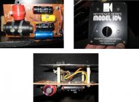
Hi guys I'm doing a restoration of my girlfriends old Kef 104, the driver units are workin fine so I will change the internal wire and Capacitors and inductors and move it to a bigger wooden board because the Auricaps where much larger then the original.
I'm not good with reading shematics so I hope you guys can help me with that, when I look on my crossover at home I can see 3 capacitors and 3 inductors, but when I look on the schematic I got from internet one of the inductors have 3 frequencies? what does that mean? I've bought the capacitors now and will change the inductors in the future but I need to know what to buy")
My first post here and I'm from Sweden so I hope you will have som understanding if I spell things wrong.
Happy New Year.
/Mattias
I'm not good with reading shematics so I hope you guys can help me with that, when I look on my crossover at home I can see 3 capacitors and 3 inductors, but when I look on the schematic I got from internet one of the inductors have 3 frequencies? what does that mean? I've bought the capacitors now and will change the inductors in the future but I need to know what to buy
My first post here and I'm from Sweden so I hope you will have som understanding if I spell things wrong.
Happy New Year.
/Mattias
Attachments
Last edited:
Welcome. Don't change the coils, in that category of commercial builds their (high enough) resistance was part of the correct crossover target analysis. The reasons are industrial economy. You can measure their DCR and order same DCR air core the most.
Maybe that woofer coil was multi tapped to be used with other models in the family. Keep it connected as originally. The Auricaps are worthwhile almost certainly.
Maybe that woofer coil was multi tapped to be used with other models in the family. Keep it connected as originally. The Auricaps are worthwhile almost certainly.
the tapped inductor
Hi Mattias,
keep that tapped inductor, at least till you hear the 104s with the new caps installed.
There should be a 3 position switch on the input terminals board on the back of the cabinet.
If it is there, it is connected to the tapped inductor.
Listen to all 3 positions of the switch after you have the new caps installed.
You may decide after extended listening to a lot of different types of recordings that you prefer one of the switch positions to the other two.
If so, then that is the one to change the inductor to.
For the inductor in the treble circuit, any new one must have the same DCR.
You can use lower DCR inductors in the bass circuit if you want a bit more bass output and slightly faster bass response,
but then you should add a resistor in Series with the capacitor in the bass circuit, or you may hear an unpleasant resonance in the lower midrange.
First listen with the new caps, then Post your findings here if you would like some follow-up advice.
Last edited:
104 versus 104ab crossover
Hi planet10,
I'm not convinced that Kef's ab version is the crossover is the best that can be done.
Audibly better may be able to be done with different, and perhaps with less, components.
I do not doubt the on-paper technically more correct response shape of the filter plus driver, but on-paper does not always equate directly with audible effects.
Ref. to Kef's Fig.2:
I think the middle diagram: "Acoustic Butterworth Circuit" may sound better than the "Practical Realization of ... Circuit".
It was clever to apply the transformation for the alternate circuit of the three capacitors, and that does result in smaller capacitances,
thus likely why Kef used that circuit,
and with the capacitors available at that time I have no doubt it sounded OK, but it may not now with modern polypropylene capacitors substituted.
For the middle circuit, C1 is 4.1uF; C2 is 12.4uF; C3 is 68.3uF.
At that time 68uF was not available in a reliable capacitor for critical audio-signal application, and the 68uF equivalents that were available did cost a lot more than the 0.6uF for the "Practical Realization ... Circuit", thus I think likely why Kef chose the latter circuit.
As regards accurate sound reproduction, I am suspect of the audible effect of the 0.6uF cap, because it will cause change to the leading edge of high frequency waveform, and particually so with a modern low ESR capacitor.
The old 0.6uF cap likely had sufficient ESR to slow down the rise time of the signal to similar rise time as through the 3.3uF and 10uF caps to not result in leading edge tizz or slight sibilence to the sound.
OK, some listeners like that change to the onset of a transient, and add 0.1uF bypass caps to their treble filters to achieve it,
however other listeners do not like that effect, and it is a sound-effect not present in the original waveform.
I don't like the sound it causes.
Now we can make a filter with 4.3uF; 12uF; 68uF from modern MKP type caps, and when I have time -{hopefully during this year}- I will try that and listen, as I have original Reference 104 with the original crossover.
Also, I have another idea to try for a slightly simpler circuit - I will post about it after I have tried it.
***************
Mattias,
did you buy 4.3uF and 5.1uF capacitors ? - or several smaller capacitances to connect in Parallel to sum to 4.2uF and 5uF ?
- and if so, what capacitance sizes did you buy ?
Last edited:
Hi planet10,
I'm not convinced that Kef's ab version is the crossover is the best that can be done. Audibly better may be able to be done with different, and perhaps with less, components.
I wouldn't argue with that, but the aB xo was definitely better than what KEF used before.
dave
Sounds like Pseudo-science to me.As regards accurate sound reproduction, I am suspect of the audible effect of the 0.6uF cap, because it will cause change to the leading edge of high frequency waveform, and particually so with a modern low ESR capacitor.
The old 0.6uF cap likely had sufficient ESR to slow down the rise time of the signal to similar rise time as through the 3.3uF and 10uF caps to not result in leading edge tizz or slight sibilence to the sound. OK, some listeners like that change to the onset of a transient, and add 0.1uF bypass caps to their treble filters to achieve it, however other listeners do not like that effect, and it is a sound-effect not present in the original waveform.
I don't like the sound it causes.
Not buying the slow waveform arguement or effects causing "tiz or sibilence". Since both the star and the delta configuration are equivalents you can substitute either with the same sound qualities. Tiz or sibilence are effects well inside the audio band and the network gave just the performance desired in the low treble regions. The fact that the circuit gave the desired response is proof that there were no significant parasitic effects in place.
You should know that I was a KEF engineer shortly after this unit was designed and can vouch for the accuracy of computer modeling at KEF, and that every 0.5 dB effect not expected (such as might come from parasitic component effects like ESR) was painstakingly tracked down. Note that even when this unit was made, a capacitor value this small would have been a film capacitor. Even if not, lower ESR capacitors have been around for the 30 years I've been in the industry.
The configuration was used because the component values made more sense than adding 68uf caps needlessly. Good engineering and a competitive market would preclude using more expensive crossover components than necessary.
This particular T network isn't widely used today, but KEF should get credit for being the first to address the issue that it isn't the electrical filter shape that we should be pursuing, but the total acoustical shape of filter and driver together.
Pulling response down in the vicinty of the tweeter's resonance will have a much greater positive sound quality effect than any supposed crossover component signature.
David Smith
Former KEF Engineer
Hi planet10,
I'm not convinced that Kef's ab version is the crossover is the best that can be done.
Audibly better may be able to be done with different, and perhaps with less, components.
I do not doubt the on-paper technically more correct response shape of the filter plus driver, but on-paper does not always equate directly with audible effects.
Ref. to Kef's Fig.2:
I think the middle diagram: "Acoustic Butterworth Circuit" may sound better than the "Practical Realization of ... Circuit".
It was clever to apply the transformation for the alternate circuit of the three capacitors, and that does result in smaller capacitances,
thus likely why Kef used that circuit,
and with the capacitors available at that time I have no doubt it sounded OK, but it may not now with modern polypropylene capacitors substituted.
For the middle circuit, C1 is 4.1uF; C2 is 12.4uF; C3 is 68.3uF.
At that time 68uF was not available in a reliable capacitor for critical audio-signal application, and the 68uF equivalents that were available did cost a lot more than the 0.6uF for the "Practical Realization ... Circuit", thus I think likely why Kef chose the latter circuit.
As regards accurate sound reproduction, I am suspect of the audible effect of the 0.6uF cap, because it will cause change to the leading edge of high frequency waveform, and particually so with a modern low ESR capacitor.
The old 0.6uF cap likely had sufficient ESR to slow down the rise time of the signal to similar rise time as through the 3.3uF and 10uF caps to not result in leading edge tizz or slight sibilence to the sound.
OK, some listeners like that change to the onset of a transient, and add 0.1uF bypass caps to their treble filters to achieve it,
however other listeners do not like that effect, and it is a sound-effect not present in the original waveform.
I don't like the sound it causes.
Now we can make a filter with 4.3uF; 12uF; 68uF from modern MKP type caps, and when I have time -{hopefully during this year}- I will try that and listen, as I have original Reference 104 with the original crossover.
Also, I have another idea to try for a slightly simpler circuit - I will post about it after I have tried it.
***************
Mattias,
did you buy 4.3uF and 5.1uF capacitors ? - or several smaller capacitances to connect in Parallel to sum to 4.2uF and 5uF ?
- and if so, what capacitance sizes did you buy ?
I bought this 5.0uF AuriCap for the Mid/bas Capacitor change: AuriCap 5 0uF 10 400V AUR505K400VA
And some cheaper capacitors from ClarityCap for the tweeter:
https://www.madisound.com/store/product_info.php?products_id=8148
https://www.madisound.com/store/product_info.php?cPath=404_5_351_353&products_id=8147
What is really wierd is that the blue capacitor on my crossover is a 4.7uF capacitor and according to the schematic it should be a 4.2 so have not ordered the last capacitor yet, is it better to pick a 3.9uF?
/Mattias
What is really wierd is that the blue capacitor on my crossover is a 4.7uF capacitor and according to the schematic it should be a 4.2 so have not ordered the last capacitor yet, is it better to pick a 3.9uF?
/Mattias
KEF tended to sort capacitors and pick non-standard values for drivers that needed a different particular vlaue. I would replace with 4.7 if that is what your unit had.
Its not worth getting too fussy over the values as the drivers can drift a little over time. It is also possible that KEF sorted through wide tolerance parts for a particular value: for example, 4.5 actual value, although marked as 4.7. You would have no way of knowing.
Get 4.7s and don't worry about it.
David S.
Thanks mate I will order 4.7 ones then.
/Mattias
options for the capacitors
Hi Mattias,
you have done things in the reverse of the usual audible priorities with the capacitors you have bought.
Usually one would would use any better audio quality caps in the tweeter filter, as any advantages would be more audible there than in the bass filter,
because the treble caps are in direct Series connection with the tweeter,
but in the bass filter that particular capacitor is a shunt bypass,
from in between two inductors to ground,
thus its audio signature is modified by the inductors to greater degree than will be the case for the caps in the treble circuit.
A modern low Dielectric Absorption capacitor, which Polypropylene caps are,
and that is otherwise well designed and not faulty in assembly will be quite adequate in the bass filter.
I would install the ClarityCap PX 5.0uF there.
That 5.0uF Auricap is ridiculously expensive for a +/- 10% Tolerance component !
With +/- 10% tolerance variations, you may get 4.5uF or 5.5uF, and worse is that you may get one of each !
... and that will cause an audible difference between the two loudspeakers.
As you have ordered 4.7uF in a +/- 5% Tolerance cap for the treble, I recommend that you send the 5.0uF Auricap back and ask for exchange for a 5.6uF polypropylene cap that is AT LEAST in +/-5% Tolerance,
plus include two 27 ohm/10 watt resistors in the order.
A 27 ohm resistor connected in Parallel with the Kef tweeter will reduce its mid-band Impedance sufficiently to allow 4.7uF and 5.6uF to work with it,
AND, the resistor will in-part reduce the effect of the tweeter's resonant frequency -{ Fs }- on the circuit.
"in-part" - it will NOT completely remove the effect of the tweeter's Fs, which is what the ab T-network does,
but it will produce a response that is towards that and better than without any resistor.
Ideally the inductor in the treble filter should be reduced a little in mH also, after the 27 ohm resistor is installed,
but for initial listening try with simply the caps changed, then Post here about the audible change.
After that you can buy a slightly smaller mH inductor for the treble circuit at the same time as you buy new inductors for the bass circuit after you have decided which of the Tap settings you and your girlfriend prefer from the large inductor.
If you like aspects of two adjacent settings of the tapped inductor, then an in-between mH inductor can be put in there, as there are plenty of options available currently.
ClarityCap PX are quite good audio quality. The Auricap may cause better sound in the treble circuit, but ONLY if it is close to its Nominal Specified capacitance, and not 4.5uF !
If both the Auricaps measure 5.5uF, or very near to that, then they will be suitable in the treble filter instead of a 5.6uF cap there,
but if they aren't near 5.5uF, or if you can't measure them, then I advise you exchange them unused, as I described above.
You do not need Auricap price components with Kef 104.
What does the seller have in 5.6uF at +/-5% Tolerance or better, at reasonable price ?
You can then obtain the 27 ohm resistors to fill your Credit balance.
If that does not entirely fill the Credit balance, then request two 2.2 ohm resistors in at least 5 watt rating
{though higher power is better to ensure they stay cool during high signal levels}.
These I will advise where to install when you buy the new inductors.
I bought this 5.0uF AuriCap for the Mid/bas Capacitor change: AuriCap 5 0uF 10 400V AUR505K400VA
And some cheaper capacitors from ClarityCap for the tweeter:
https://www.madisound.com/store/product_info.php?products_id=8148
https://www.madisound.com/store/product_info.php?cPath=404_5_351_353&products_id=8147
What is really wierd is that the blue capacitor on my crossover is a 4.7uF capacitor and according to the schematic it should be a 4.2 so have not ordered the last capacitor yet, is it better to pick a 3.9uF?
/Mattias
Hi Mattias,
you have done things in the reverse of the usual audible priorities with the capacitors you have bought.
Usually one would would use any better audio quality caps in the tweeter filter, as any advantages would be more audible there than in the bass filter,
because the treble caps are in direct Series connection with the tweeter,
but in the bass filter that particular capacitor is a shunt bypass,
from in between two inductors to ground,
thus its audio signature is modified by the inductors to greater degree than will be the case for the caps in the treble circuit.
A modern low Dielectric Absorption capacitor, which Polypropylene caps are,
and that is otherwise well designed and not faulty in assembly will be quite adequate in the bass filter.
I would install the ClarityCap PX 5.0uF there.
That 5.0uF Auricap is ridiculously expensive for a +/- 10% Tolerance component !
With +/- 10% tolerance variations, you may get 4.5uF or 5.5uF, and worse is that you may get one of each !
... and that will cause an audible difference between the two loudspeakers.
As you have ordered 4.7uF in a +/- 5% Tolerance cap for the treble, I recommend that you send the 5.0uF Auricap back and ask for exchange for a 5.6uF polypropylene cap that is AT LEAST in +/-5% Tolerance,
plus include two 27 ohm/10 watt resistors in the order.
A 27 ohm resistor connected in Parallel with the Kef tweeter will reduce its mid-band Impedance sufficiently to allow 4.7uF and 5.6uF to work with it,
AND, the resistor will in-part reduce the effect of the tweeter's resonant frequency -{ Fs }- on the circuit.
"in-part" - it will NOT completely remove the effect of the tweeter's Fs, which is what the ab T-network does,
but it will produce a response that is towards that and better than without any resistor.
Ideally the inductor in the treble filter should be reduced a little in mH also, after the 27 ohm resistor is installed,
but for initial listening try with simply the caps changed, then Post here about the audible change.
After that you can buy a slightly smaller mH inductor for the treble circuit at the same time as you buy new inductors for the bass circuit after you have decided which of the Tap settings you and your girlfriend prefer from the large inductor.
If you like aspects of two adjacent settings of the tapped inductor, then an in-between mH inductor can be put in there, as there are plenty of options available currently.
ClarityCap PX are quite good audio quality. The Auricap may cause better sound in the treble circuit, but ONLY if it is close to its Nominal Specified capacitance, and not 4.5uF !
If both the Auricaps measure 5.5uF, or very near to that, then they will be suitable in the treble filter instead of a 5.6uF cap there,
but if they aren't near 5.5uF, or if you can't measure them, then I advise you exchange them unused, as I described above.
You do not need Auricap price components with Kef 104.
What does the seller have in 5.6uF at +/-5% Tolerance or better, at reasonable price ?
You can then obtain the 27 ohm resistors to fill your Credit balance.
If that does not entirely fill the Credit balance, then request two 2.2 ohm resistors in at least 5 watt rating
{though higher power is better to ensure they stay cool during high signal levels}.
These I will advise where to install when you buy the new inductors.
Last edited:
Hi Mattias,
you have done things in the reverse of the usual audible priorities with the capacitors you have bought.
Usually one would would use any better audio quality caps in the tweeter filter, as any advantages would be more audible there than in the bass filter,
because the treble caps are in direct Series connection with the tweeter,
but in the bass filter that particular capacitor is a shunt bypass,
from in between two inductors to ground,
thus its audio signature is modified by the inductors to greater degree than will be the case for the caps in the treble circuit.
A modern low Dielectric Absorption capacitor, which Polypropylene caps are,
and that is otherwise well designed and not faulty in assembly will be quite adequate in the bass filter.
I would install the ClarityCap PX 5.0uF there.
That 5.0uF Auricap is ridiculously expensive for a +/- 10% Tolerance component !
With +/- 10% tolerance variations, you may get 4.5uF or 5.5uF, and worse is that you may get one of each !
... and that will cause an audible difference between the two loudspeakers.
As you have ordered 4.7uF in a +/- 5% Tolerance cap for the treble, I recommend that you send the 5.0uF Auricap back and ask for exchange for a 5.6uF polypropylene cap that is AT LEAST in +/-5% Tolerance,
plus include two 27 ohm/10 watt resistors in the order.
A 27 ohm resistor connected in Parallel with the Kef tweeter will reduce its mid-band Impedance sufficiently to allow 4.7uF and 5.6uF to work with it,
AND, the resistor will in-part reduce the effect of the tweeter's resonant frequency -{ Fs }- on the circuit.
"in-part" - it will NOT completely remove the effect of the tweeter's Fs, which is what the ab T-network does,
but it will produce a response that is towards that and better than without any resistor.
Ideally the inductor in the treble filter should be reduced a little in mH also, after the 27 ohm resistor is installed,
but for initial listening try with simply the caps changed, then Post here about the audible change.
After that you can buy a slightly smaller mH inductor for the treble circuit at the same time as you buy new inductors for the bass circuit after you have decided which of the Tap settings you and your girlfriend prefer from the large inductor.
If you like aspects of two adjacent settings of the tapped inductor, then an in-between mH inductor can be put in there, as there are plenty of options available currently.
ClarityCap PX are quite good audio quality. The Auricap may cause better sound in the treble circuit, but ONLY if it is close to its Nominal Specified capacitance, and not 4.5uF !
If both the Auricaps measure 5.5uF, or very near to that, then they will be suitable in the treble filter instead of a 5.6uF cap there,
but if they aren't near 5.5uF, or if you can't measure them, then I advise you exchange them unused, as I described above.
You do not need Auricap price components with Kef 104.
What does the seller have in 5.6uF at +/-5% Tolerance or better, at reasonable price ?
You can then obtain the 27 ohm resistors to fill your Credit balance.
If that does not entirely fill the Credit balance, then request two 2.2 ohm resistors in at least 5 watt rating
{though higher power is better to ensure they stay cool during high signal levels}.
These I will advise where to install when you buy the new inductors.
Ok I was told it is better to have a better capacitor in the mid/bas that's why I bought the Auricaps for the mid/bas, they are factory matched pairs if that's helps? should I put the Auricaps in the tweeter instead and go for the ClarityCaps int the mid/bas?
Is this a better choice instead of tha Auricap? http://www.audiocap.co.uk/47uf-630v-ampohm-metallized-polypropylene-audio-capacitor-110-p.asp
Mattias
Last edited:
Hi guys I'm confused and this is getting complicated for me and I'm not so good at this
I want to in a simple and not to expensive way change the capacitors in my crossover to get a better sound, I don't want to add things just change the capacitors so what should I buy?
I'm still confused about the 4.2uF caps that is connected to the tweeter on the schematic and on my crossover it's 4,7uF caps, some people say it's not that big issue and some do So should I try yo get caps that is near 4.2?
Tweeter: 4.2uF
4.3uF Claritycap ESA Range polypropylene Tolerance:..............................+/- 3%
4.4uF Claritycap SA Range polypropylene
Tolerance:..............................+/- 5%
Or 4.7uF from same make?
I could change my Auricaps to these ones from Ampohm if I wanted.
4.7uF 630V Ampohm Metallized Polypropylene Audio Capacitor
+/- 5%
Tweeter: 5.0uF
ClarityCap 5.0 mfd PX Range Polypropylene Caps
Tolerance +/-5%
Bas/mid: 5.0uF
ClarityCap 5.0 mfd PX Range Polypropylene Caps
Tolerance +/-5%
Is it possible to use 4.7caps where it should be 5.0uF ones? It's hard to find 5.0uF caps, or 4.7uF + 0.33uF?
Please help me out guys and I'm sorry if I'm a pain in the*** now
/Mattias
I want to in a simple and not to expensive way change the capacitors in my crossover to get a better sound, I don't want to add things just change the capacitors so what should I buy?
I'm still confused about the 4.2uF caps that is connected to the tweeter on the schematic and on my crossover it's 4,7uF caps, some people say it's not that big issue and some do
So should I try yo get caps that is near 4.2?Tweeter: 4.2uF
4.3uF Claritycap ESA Range polypropylene Tolerance:..............................+/- 3%
4.4uF Claritycap SA Range polypropylene
Tolerance:..............................+/- 5%
Or 4.7uF from same make?
I could change my Auricaps to these ones from Ampohm if I wanted.
4.7uF 630V Ampohm Metallized Polypropylene Audio Capacitor
+/- 5%
Tweeter: 5.0uF
ClarityCap 5.0 mfd PX Range Polypropylene Caps
Tolerance +/-5%
Bas/mid: 5.0uF
ClarityCap 5.0 mfd PX Range Polypropylene Caps
Tolerance +/-5%
Is it possible to use 4.7caps where it should be 5.0uF ones? It's hard to find 5.0uF caps, or 4.7uF + 0.33uF?
Please help me out guys and I'm sorry if I'm a pain in the*** now
/Mattias
Last edited:
I found these capacitors with +/-1% tolerance
Dayton Precision 1% Metallized Polypropylene Capacitors at Parts Express
I can get them in 2.2uf + 2.0uF and 3.0uF + 2.0uF how about that?
/Mattias
Dayton Precision 1% Metallized Polypropylene Capacitors at Parts Express
I can get them in 2.2uf + 2.0uF and 3.0uF + 2.0uF how about that?
/Mattias
Hi guys I'm confused and this is getting complicated for me and I'm not so good at this
I want to in a simple and not to expensive way change the capacitors in my crossover to get a better sound, I don't want to add things just change the capacitors so what should I buy?
I'm still confused about the 4.2uF caps that is connected to the tweeter on the schematic and on my crossover it's 4,7uF caps, some people say it's not that big issue and some do
/Mattias
Well, now you have to decide whether spending a lot of money to get some exact value, overpriced capacitor to replace the caps in a 30 year old speaker (probably still good caps, by the way) will give you sonic nirvana, or whether it is sort of silly.
Hmmm?
David S.
Well, now you have to decide whether spending a lot of money to get some exact value, overpriced capacitor to replace the caps in a 30 year old speaker (probably still good caps, by the way) will give you sonic nirvana, or whether it is sort of silly.
Hmmm?
David S.
Is there a middle ground?
I can spend $90/£58 on the capacitors
/Mattias
Apology and Correction - not 27 ohms !
Mattias,
I apologise, there is a mistake in my Post #12 of yesterday.
I recommended a 27 ohm resistor - [as in the Quote I have pasted above] .
That is the incorrect resistance.
The correct resistance is 56 ohms.
This came into my mind later, but I was not able to get access to a computer again till now.
{27 ohm is the compensation resistor for a project I am working on, thus why 27 ohms was in my mind.}
For 56 ohms in Parallel with the Kef tweeter there will be little current through the resistor,
thus less power dissipated in that resistor,
thus a 5 watt rated resistor will be sufficient, but if the seller has only in higher powers that is OK.
If no 56 ohms, then buy the nearest resistance larger, such as 62 ohms,
but not as high as 68 ohms because that will be too high for there to be sufficient compensation effect.
56 ohms in 5 watts or larger power is quite common. One simply has to look for sellers.
***************
I will now read the new posts since my last here, and reply when I have time available.
plus include two 27 ohm/10 watt resistors in the order.
A 27 ohm resistor connected in Parallel with the Kef tweeter will reduce its mid-band Impedance sufficiently to allow 4.7uF and 5.6uF to work with it,
AND, the resistor will in-part reduce the effect of the tweeter's resonant frequency -{ Fs }- on the circuit.
"in-part" - it will NOT completely remove the effect of the tweeter's Fs, which is what the ab T-network does,
but it will produce a response that is towards that and better than without any resistor.
Ideally the inductor in the treble filter should be reduced a little in mH also, after the 27 ohm resistor is installed,
but for initial listening try with simply the caps changed, then Post here about the audible change.
Mattias,
I apologise, there is a mistake in my Post #12 of yesterday.
I recommended a 27 ohm resistor - [as in the Quote I have pasted above] .
That is the incorrect resistance.
The correct resistance is 56 ohms.
This came into my mind later, but I was not able to get access to a computer again till now.
{27 ohm is the compensation resistor for a project I am working on, thus why 27 ohms was in my mind.}
For 56 ohms in Parallel with the Kef tweeter there will be little current through the resistor,
thus less power dissipated in that resistor,
thus a 5 watt rated resistor will be sufficient, but if the seller has only in higher powers that is OK.
If no 56 ohms, then buy the nearest resistance larger, such as 62 ohms,
but not as high as 68 ohms because that will be too high for there to be sufficient compensation effect.
56 ohms in 5 watts or larger power is quite common. One simply has to look for sellers.
***************
I will now read the new posts since my last here, and reply when I have time available.
Last edited:
What measured capacitance ?
Hi again Mattias,
they may be a factory matched pair, BUT what is the measured capacitance ?
They could be a matched 4.5uF pair, or a matched 5.5uF pair,
or any matched pair of numbers that is within +/- 10% of 5uF.
You need to know their measured capacitance to be able to decide now where is best to use them,
and if other modifications may be necessary.
You paid for a matched pair, therefore you are entitled to know what their measured value is.
If the seller will not tell you the measured value then send them back and ask for a Refund,
because a +/- 10% Tolerance capacitor is of little use in a crossover that has to work in the midrange,
which is what the 104 crossover is.
Whether Ampohm is better or not than Auricap, or than any other brand of well-made metallized polypropylene capacitor, one will have to decide by listening.
It is more important to use the optimum values of measured capacitance, than to be concerned about some of the brand names.
A few brands seem to have batch variations with some samples poorly assembled, and results with those can be audibly unpleasant.
"Solen" and "Bennic" brands are reported by a lot of users to be not as good in midrange and treble sounds as the other brands that have been mentioned in this thread.
"Dayton" is made by Bennic, and for the Dayton Precision range the price is for the +/- 1% Tolerance.
I think that ClarityCap PX series is quite good enough for Kef 104 and good in general.
I use them, and have no problems with them.
, they are factory matched pairs if that's helps?
Is this a better choice instead of tha Auricap? 4 7uF 630V Ampohm Metallized Polypropylene Audio Capacitor
Mattias
Hi again Mattias,
they may be a factory matched pair, BUT what is the measured capacitance ?
They could be a matched 4.5uF pair, or a matched 5.5uF pair,
or any matched pair of numbers that is within +/- 10% of 5uF.
You need to know their measured capacitance to be able to decide now where is best to use them,
and if other modifications may be necessary.
You paid for a matched pair, therefore you are entitled to know what their measured value is.
If the seller will not tell you the measured value then send them back and ask for a Refund,
because a +/- 10% Tolerance capacitor is of little use in a crossover that has to work in the midrange,
which is what the 104 crossover is.
Whether Ampohm is better or not than Auricap, or than any other brand of well-made metallized polypropylene capacitor, one will have to decide by listening.
It is more important to use the optimum values of measured capacitance, than to be concerned about some of the brand names.
A few brands seem to have batch variations with some samples poorly assembled, and results with those can be audibly unpleasant.
"Solen" and "Bennic" brands are reported by a lot of users to be not as good in midrange and treble sounds as the other brands that have been mentioned in this thread.
"Dayton" is made by Bennic, and for the Dayton Precision range the price is for the +/- 1% Tolerance.
I think that ClarityCap PX series is quite good enough for Kef 104 and good in general.
I use them, and have no problems with them.
Last edited:
confused, and why ...
Hi again Mattias,
I am not surprised that you are confused, and you are correct in saying that you are not good at this.
I think you have been lead by too many opinions about differences in sound between brands of capacitors being able to improve the sound of loudspeaker systems for which another matter has to be addressed to actually cause a real improvement.
Kef addressed the other matter when trying to improve the original 104, and their result is the 104ab.
If you like the sound of the original 104, then copy EXACTLY the capacitances that are in the Specification
for it, OR, as close as you can buy to those.
Closest available now is 4.3uF and 5.0uF, or 5.1uF in some brands.
Those will work.
Buy in +/- 5% Tolerance- that will get you close enough.
I recommend that you do not use 4.7uF unless you intall the 56 ohm resistor I described.
If you use the 56 ohm Parallel connected resistor, then use 4.7uF and 5.6uF in the treble filter, and 5uF in the bass filter.
This will give you an improvement in midrange coherence over the old 104 design and towards the 104ab design.
This will cause a more significant audible result than any expensive capacitor priced higher than ClarityCap PX series.
I recommend that you do NOT use 4.7uF + 0.33uF in Parallel to create the 5uF cap.
This is a complicated topic, and may confuse you more.
Save the remainder of your money to use for better inductors later,
for after you have listened with the new capacitors installed,
and decided about the switched/tapped bass-mid inductor position.
That is the best "middle ground" I can think of.
Hi guys I'm confused and this is getting complicated for me and I'm not so good at this
I want to in a simple and not to expensive way change the capacitors in my crossover to get a better sound, I don't want to add things just change the capacitors so what should I buy?
I'm still confused about the 4.2uF caps that is connected to the tweeter on the schematic and on my crossover it's 4,7uF caps, some people say it's not that big issue and some do
It's hard to find 5.0uF caps, or 4.7uF + 0.33uF?
Please help me out guys and I'm sorry if I'm a pain in the*** now
/Mattias
Hi again Mattias,
I am not surprised that you are confused, and you are correct in saying that you are not good at this.
I think you have been lead by too many opinions about differences in sound between brands of capacitors being able to improve the sound of loudspeaker systems for which another matter has to be addressed to actually cause a real improvement.
Kef addressed the other matter when trying to improve the original 104, and their result is the 104ab.
If you like the sound of the original 104, then copy EXACTLY the capacitances that are in the Specification
for it, OR, as close as you can buy to those.
Closest available now is 4.3uF and 5.0uF, or 5.1uF in some brands.
Those will work.
Buy in +/- 5% Tolerance- that will get you close enough.
I recommend that you do not use 4.7uF unless you intall the 56 ohm resistor I described.
If you use the 56 ohm Parallel connected resistor, then use 4.7uF and 5.6uF in the treble filter, and 5uF in the bass filter.
This will give you an improvement in midrange coherence over the old 104 design and towards the 104ab design.
This will cause a more significant audible result than any expensive capacitor priced higher than ClarityCap PX series.
I recommend that you do NOT use 4.7uF + 0.33uF in Parallel to create the 5uF cap.
This is a complicated topic, and may confuse you more.
Save the remainder of your money to use for better inductors later,
for after you have listened with the new capacitors installed,
and decided about the switched/tapped bass-mid inductor position.
That is the best "middle ground" I can think of.
Last edited:
- Home
- Loudspeakers
- Multi-Way
- Kef 104 Crossover help.