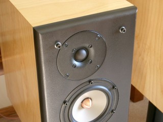
Hi, I'm building my first speaker system and I'm really excited. I chose to use the Seas T25CF as the tweeter and the W15CY as the midwoofer.
1) How do I determine the optimal crossover frequency?
2) The T25CF has an impedance of 6 ohms while the W15CY has an impedance of 8 ohms, is this going to be a problem?
I have probably have more questions later.
Thanks!
1) How do I determine the optimal crossover frequency?
2) The T25CF has an impedance of 6 ohms while the W15CY has an impedance of 8 ohms, is this going to be a problem?
I have probably have more questions later.
Thanks!
Good questions!
1) The W15CY is small and will play high, so that gives you some leeway. My 1st guess would be about 2500Hz, 2nd order. Both drivers tend to naturally roll off around 2-2.5K, so that's a good starting point.
2) No. You just have to pick crossover parts to match the drivers.
I'm sure someone here has used these drivers to good effect, let's see if they chime in.
Crossover point is going to come down to a bit of personal preference, but I've got a system with the same drivers. The T25 has good distortion performance low, so you can cross it down between 1500 and 2000. LR2 electrical works great, add a deep notch at the woofer's breakup peak and pad the tweeter down a bit and you're set.
The Parts Express 3/8 cubic foot boxes are perfect for a ported application (or similar size). Even if you are going to cross to a sub, I suggest ported to keep the W15 excursion down. Bottom line - you'll be able to get louder cleaner with a ported alignment.
You'll get a very nice system when done properly with these drivers. You will definitely hear the difference between amplifiers. Give them a good amp and you will be rewarded.
In a big room, you will want to turn them into a three way with a bass bin running up to 150-300 Hz, but that can be a second project. Mine are actively crossed at 160 Hz LR4 and the max SPL limit is my desire to maintain my hearing.
Hi,
For your first build just copy something done with your preferred driver
by someone who knows what they are doing and wonder about the
why's and wherefore's as you build it, it makes far more sense.
Monitor W15NeoSEAS W15CY001 +
W15CY001-OWI
Zaph|Audio : indicates a problem issue to be taken seriously.
You may have a lot more fun building this first off :
Zaph|Audio - ZMV5 - MCM / Vifa 5" System
(Note the w15 won't resolve the bass level issues much, its driver size related.)
rgds, sreten.
http://sites.google.com/site/undefinition/diy
http://www.zaphaudio.com
http://www.rjbaudio.com/Audiofiles/FRDtools.html
http://www.rjbaudio.com/
http://speakerdesignworks.com/
http://www.htguide.com/forum/showthread.php4?t=28655
http://www.humblehomemadehifi.com
http://www.troelsgravesen.dk/Diy_Loudspeaker_Projects.htm
http://www.quarter-wave.com/
http://www.frugal-horn.com/
http://www.linkwitzlab.com/
http://www.musicanddesign.com/
Last edited:
But, how about inductors and resistors? Do they follow the same concept? Do they also have a tolerance?
Everything produced has a tolerance. Resistors come mainly with 1, 2 and 5% tolerance. For inductors, apart the tolerance factor, there is the possibility to have any value you need, simply buying a larger value and unwind the wire (and measure).
Ralf
For your first build just copy something done with your preferred driver
by someone who knows what they are doing and wonder about the
why's and wherefore's as you build it, it makes far more sense.
I can agree on that, but the fun in building our own design is IMHO more rewarding. The problem is that the possibility to do something wrong is high, and choosing to do the first build with expensive drivers is not a good idea.
If you choose to design your speaker, sreten has provided you with some good links. Fortunately there is free software for design (look at FRD tools), and a good mic doesn't cost an arm and a leg.
Ralf
Hi,
IMO its no fun realising after the fact (of the build), there is more to it than
you first thought, and that is why the speakers (expensive drivers or not),
do not sound as good as you expected, but it is your / anyones choice.
Expensive drivers (when there are so many better value drivers) is not
the way to start. Work your way up to it. People will buy any good
jobs you do on the way just to have something bespoke / original.
rgds, sreten.
Hi,
I have done a lot of research and calculations and so I have faith in my own design. In addition, sometimes, you learn more with errors (if there are any).
Nonetheless, I'm still working on my crossover design. I have completed two designs; 2nd order and a 3rd order. I would like to assemble these and test for sonic differences. However, I notice that for me to get the right values for the components (caps/inductors/resistors), I would have to have a series or parallels of components to achieve the desired value. I was wondering if there's something I can do; the problem with having tons of series and parallels is that it's not very cost-efficient and also, it takes up the inner enclosure volume which forces me to recalculate the ideal enclosure volume.
I have the 2 designs here for anyone who would like to give me any feedback. I would really appreciate it.
Thanks guys!
I have done a lot of research and calculations and so I have faith in my own design. In addition, sometimes, you learn more with errors (if there are any).
Nonetheless, I'm still working on my crossover design. I have completed two designs; 2nd order and a 3rd order. I would like to assemble these and test for sonic differences. However, I notice that for me to get the right values for the components (caps/inductors/resistors), I would have to have a series or parallels of components to achieve the desired value. I was wondering if there's something I can do; the problem with having tons of series and parallels is that it's not very cost-efficient and also, it takes up the inner enclosure volume which forces me to recalculate the ideal enclosure volume.
I have the 2 designs here for anyone who would like to give me any feedback. I would really appreciate it.
An externally hosted image should be here but it was not working when we last tested it.
An externally hosted image should be here but it was not working when we last tested it.
Thanks guys!
Hi,
I have done a lot of research and calculations and so I have faith in my own
design. In addition, sometimes, you learn more with errors (if there are any).
Thanks guys!
Hi,
To be frank simply not enough research into the correct design methods.
I have no faith in your "design". The conjugate impedance circuits on the
bass are simply unnecessary (and wrong ? without a specified sealed box),
they also seem likely unnecessary for the ferrrofluid damped tweeter.
Neither design will work correctly with real drivers in real boxes.
There is no baffle step compensation for your boxes.
There are no trap circuits for the bass/mids peak around 8kHz.
What matters is the acoustic transfer functions, not the electrical.
All in all seems too much studying of "crossovers" in books and not
enough studying of the proper way of doing it, with or without
measurements, as illustrated e.g. in most of the links I provided.
Forget the text book stuff, look at some real designs done properly.
With such expensive drivers, proper modelling is the only way to do it.
Make sure you have the correct data for your bass/mid driver, the
data for the older version is here : (newer in the other tests)
Zaph|Audio
If it seems I'm being overly critical, I think for such drivers I should be.
rgds, sreten.
Read the FAQs here : http://sites.google.com/site/undefinition/diy
http://www.rjbaudio.com/Audiofiles/FRDtools.html
Last edited:
Let's see if we can help our friend learn about real world crossover design. What we care about is the acoustic response, not the electrical filter shape. Unless the drivers are flat well beyond their operating range you will need to consider the combined effect of the driver and crossover response.
If you search the net you'll find add on baffle step circuits. That works, or you can increase the value of the first inductor in the woofer circuit and get the same effect. Either way works, but using the single larger inductor means you'll have less loss both in system sensitivity and your wallet. Similarly, you can often adjust the values of the components in parallel with the driver to compensate for changing driver impedance and avoid the cost of a tuned circuit that often requires large values.
Play with your simulator to see what happens when you change a component to the nearest standard value. Remember that crossover parts typically have 10% or 20% tolerances, so for practical purposes you need to calculate only two significant digits.
When your simulator comes up with 1000+ uF and 9 mH in your zoebel it is trying to tell you don't bother. 1000 uF provides very low impedance for audio frequencies - you could replace it with a wire. Then 9 mH has very high impedance for most audio frequencies. Replace it with an open. Hmm.
The "second order" woofer network is close. Lose C5-R5 and bump L3 up at least 50% to provide some baffle step as Sreten suggests. Try it without C4. Sure it looks like first order but when combined with the woofer response you'll get at least a second order roll off. Use C6-L4-R6 to notch out the woofer's breakup. Try R5=0 and see what happens. You should end up with a 4th order acoustic response crossing around 1600 Hz with a 50+dB deep notch at the breakup peak.
On the tweeter network you don't need the fancy stuff, just C1, L1, R3 and R4. There is a standard value cap and inductor that works well. When combined with the tweeter response you'll end up with a 4th order acoustic response.
In my system, it's all standard parts except for L4, where I had to unwind a few turns to raise the notch frequency.
Are you going to measure and tweak or just simulate and build? What size is your enclosure? (That plays into the baffle step equation)
Hi,
The topology suggested above is very near : Zaph|Audio
Note the use of the trap circuit to shape the crossover function.
This must match the correct version of the driver to work well.
Note the result is 4th order L/R acoustic. You should follow this.
rgds, sreten.
Box should be around 6L for sealed or
around 10L tuned to 40Hz vented.
Last edited:
Perfect - Thanks for finding that, which is exactly the topology I was trying to describe.
The values in that circuit are very close to those used in my Zaph designed system. (no big surprise)
Hi,
Yes, he pulled your design because its for the older version of the driver,
with the peak around 6kHz, that probably explains the 1.6kHz c/o point.
rgds, sreten.
Last edited:
Let's see if we can help our friend learn about real world crossover design. What we care about is the acoustic response, not the electrical filter shape. Unless the drivers are flat well beyond their operating range you will need to consider the combined effect of the driver and crossover response.
If you search the net you'll find add on baffle step circuits. That works, or you can increase the value of the first inductor in the woofer circuit and get the same effect. Either way works, but using the single larger inductor means you'll have less loss both in system sensitivity and your wallet. Similarly, you can often adjust the values of the components in parallel with the driver to compensate for changing driver impedance and avoid the cost of a tuned circuit that often requires large values.
Play with your simulator to see what happens when you change a component to the nearest standard value. Remember that crossover parts typically have 10% or 20% tolerances, so for practical purposes you need to calculate only two significant digits.
When your simulator comes up with 1000+ uF and 9 mH in your zoebel it is trying to tell you don't bother. 1000 uF provides very low impedance for audio frequencies - you could replace it with a wire. Then 9 mH has very high impedance for most audio frequencies. Replace it with an open. Hmm.
The "second order" woofer network is close. Lose C5-R5 and bump L3 up at least 50% to provide some baffle step as Sreten suggests. Try it without C4. Sure it looks like first order but when combined with the woofer response you'll get at least a second order roll off. Use C6-L4-R6 to notch out the woofer's breakup. Try R5=0 and see what happens. You should end up with a 4th order acoustic response crossing around 1600 Hz with a 50+dB deep notch at the breakup peak.
On the tweeter network you don't need the fancy stuff, just C1, L1, R3 and R4. There is a standard value cap and inductor that works well. When combined with the tweeter response you'll end up with a 4th order acoustic response.
In my system, it's all standard parts except for L4, where I had to unwind a few turns to raise the notch frequency.
Are you going to measure and tweak or just simulate and build? What size is your enclosure? (That plays into the baffle step equation)
I'm using a custom enclosure based on the ideal volume calculation of the woofer. It is 11.2 L and with F3 at 41Hz.
As you can tell, I'm trying to avoid "kits" because I'm trying to create a set of bookshelves speakers entirely on my own design. However, I have taken your advise in account. I suppose its wiser to invest in cheaper drivers for the moment and do concentrate on a much more simpler crossover design. In through measurements and critical listening, perhaps I can improve the crossover circuitry later on.
So, you suggest that I can simply just remove the fancy components and concentrate on the "true" 2nd crossover design? And when needed, I'll just add other types of networks on top? As far as crossover design, do people always rely on existent designs and it's up to them to tweak them? Or do some people design crossover on their completely from scratch (like what I'm trying to do)?
Thank you for the great response.
I have the 2 designs here for anyone who would like to give me any feedback. I would really appreciate it.
You never made it clear how you derived these designs. Are these real networks based on some acoustical measurements of the drivers on the cabinets intended? Or are they based on similar drivers on somebody elses cabinets, of different dimensions than your own? Or are they theoretical electrical networks to ideal targets (Butterworth, LR etc.).
If the later is the case you will find that the end result is not likely to work nearly as well as you like. As the guys explained the best approach is to design an electrical network that takes the actual response of the units on your cabinets. It must take into account the impedance curve of the drivers as a real load to the networks. The combination of all these factors then needs to be adjusted (optimized) to hit target function shapes that will add together well, including compensating for the effects of woofer depth (phase delay).
Without all these factors you are much better off copying someone elses design (like Zaph Audio's) exactly.
David S.
As far as crossover design, do people always rely on existent designs and
it's up to them to tweak them? Or do some people design crossover on
their completely from scratch (like what I'm trying to do)?
Hi,
No. I've posted enough links to describe how to do it completely from
scratch if you can measure, or for the simulation case, manafactures
curves on a flat baffle or better still Zaphs flat baffle measurements.
Still there is nothing original in good speaker design, whether its following
a good crossover topology, good acoustic c/o functions, a bass alignment
or any other detail that has nearly always been done before in some form.
If you cannot build current racing cars, you cannot design a good new one.
rgds, sreten.
You may have a lot more fun building this first off :
Zaph|Audio - ZMV5 - MCM / Vifa 5" System
Its not as good (well better so far) as you are
now considering for a fraction of the total price.
VFM is excellent, but it is compromised slightly.
Last edited:
- Status
- This old topic is closed. If you want to reopen this topic, contact a moderator using the "Report Post" button.
- Home
- Loudspeakers
- Multi-Way
- Buidling my first speaker system but I have crossover questions