i bought one commercial 4 th order linkwitz passive crossover. But there is almost 20% shift in crossover frequency.
It is designed for 1.8k & it is showing 2.4k at -3db. .
The MKP capacitors are +/- 5%. Anybody here built 4 the order passive crossover. All suggestions to make this properly are welcome.
It is designed for 1.8k & it is showing 2.4k at -3db. .
The MKP capacitors are +/- 5%. Anybody here built 4 the order passive crossover. All suggestions to make this properly are welcome.
You Probably need to add a zobel network to the low frequency driver to keep its impedance constant at the crossover frequency.
Rob Elliot has a good article on passive crossovers here.
Passive Crossover Network Design
Basicaly this means adding a resistor and capacitor to the crossover circuit.")
You may not need to do this with your HF depending on its design.
It might be useful to post any detais you have of the crossover, and the drivers that you are using.
Rob Elliot has a good article on passive crossovers here.
Passive Crossover Network Design
Basicaly this means adding a resistor and capacitor to the crossover circuit.
You may not need to do this with your HF depending on its design.
It might be useful to post any detais you have of the crossover, and the drivers that you are using.
Hey jayam000, you should start by publishing your driver(s) specs/T/S/data, and next your crossover circuit diagram. If not, help it's close to impossible (just words, here, don't play a thing with electronics).i bought one commercial 4 th order linkwitz passive crossover. But there is almost 20% shift in crossover frequency.
It is designed for 1.8k & it is showing 2.4k at -3db. .
The MKP capacitors are +/- 5%. Anybody here built 4 the order passive crossover. All suggestions to make this properly are welcome.
a Butterworth is a single pole filter. The Q is 1/sqrt(2) = 0.707
A two pole Linkwitz Reilly is two Butterworth cascaded to give a Q=0.5
When you cascade two Butterworth together (ensuring that both filters are correctly loaded) the -3dB at the roll off frequencies add up to -6dB (that I believe is equivalent to saying Q=0.5).
Now combine an LC for a 2pole Butterworth filter. This still has the same Q=0.707 (that's what makes it Butterworth) but it rolls off out of the passband at 40dB/decade.
Cascade a pair of these 2pole Butterworth and you get a 4pole Linkwitz with Q=0.5 and the rolloff frequency again has a cut off of -6dB.
But there is a problem.
The standard formula for modeling a filter assumes that the source impedance is zero and the load impedance is infinity (equivalent to an open circuit).
Loudspeaker crossovers modify the component values to allow for an 8ohm load impedance.
If you cascade two of these filters the component values need to be corrected further to take account of the incorrect source and loading assumptions.
Finally, if the 4pole LR filter has been designed for that particular driver then it has already had it's component values altered to suit the changing impedance presented by that matching driver.
If you buy a generic crossover and fit any substitute driver, the loading will be different and as a result the crossover will be inaccurate.
This is where a speaker designer (box & drivers & crossover) earns his keep.
Last edited:
I'm confused as of how you "measure" the -3dB. Are you sure you have measured what you wanted to measure? If you have the equipment for measurement, you should be able to redesign the crossover, no?
Okay, let's assume you don't have any equipment. I haven't seen a ready-made crossover in detail. I hope I'm not wrong but let me guess that the woofer filter will have ONLY 4 components (Lw1/Cw1/Lw2/Cw2), and the tweeter filter will have also ONLY 4 components (Ct1/Lt1/Ct2/Lt2).
The drift you mention is most probably due to drivers incompatibility in impedance and sensitivity, so this is what you should do:
1. If your woofer (nominal) impedance is (said) 8 Ohm, how about the tweeter? If the tweeter nominal impedance is 6 Ohm, add a 2.2 Ohm resistor in series with the tweeter (just before the tweeter) so to match them.
2. Now you want to match your tweeter sensitivity with the woofer. The tweeter is almost always more sensitive than the woofer. You add a series resistor before Ct1. The value is based on your listening (the tweeter should not be louder than the woofer). 10, 8.2, 6.8, 5.6 or 4.7 Ohm are possible.
3. Now you want to fix the bump in the woofer just before the crossover frequency. Add a resistor in series with Cw1. Most probably 4.7 Ohm or 3.3 Ohm or 2.2 Ohm.
i bought one commercial 4 th order linkwitz passive crossover. But there is almost 20% shift in crossover frequency.
It is designed for 1.8k & it is showing 2.4k at -3db. .
The MKP capacitors are +/- 5%. Anybody here built 4 the order passive crossover. All suggestions to make this properly are welcome.
Can you get your money back?
Commercial off-the-shelf crossovers are useless. Unfortunately, you need to design one from scratch or you will have the problems you are experiencing.
The reason for the shift is probably due somewhat to component variation, but more likely due to the drivers connected to it.
The drivers are not at fault, but how can you expect to design a universal crossover when every driver sold has a different impedance and inductance curve vs. frequency?
The answer is, you can't. the reason is that the driver's impedance and inductance vary with frequency. The amount of variation and where they vary are different for every type of driver, almost like fingerprints.
You may be able to shift the crossover point, but I guarantee you that you will never get it to sound anywhere near HiFi quality. The difference between a properly designed crossover and what you have is going to be like night and day.
Relax, everyone. Don't scare Jayam000
Actually, it is not "that" bad. Fourth order Linkwitz-Riley has a unique property that make it possible to be a "universal" crossover. The phase tracking is the most important one. You can have a good speaker with ready-made LR4 crossover as long as you match the impedance and sensitivity using resistors.
It is true that the difference between it and a properly designed crossover can be like night and day. But "properly designed" crossovers are very rare.
It's like comparing a parallel crossover with series one. While I strongly believe that properly designed parallel crossover will beat a properly designed series crossover, in practice many cannot prove it. The LR4 and the ARSXO (Audio-Reality Series Crossover) are two examples of quick design with acceptable result (tho not the best).
Relax, everyone. Don't scare Jayam000
Actually, it is not "that" bad. Fourth order Linkwitz-Riley has a unique property that make it possible to be a "universal" crossover. The phase tracking is the most important one. You can have a good speaker with ready-made LR4 crossover as long as you match the impedance and sensitivity using resistors.
Jay, that presumes that the components in the COTS crossover are quality.
I am not so sure about 4th order being so unique as to insure quality. In my mind, I just visualize all those components in series before each driver and see the opportunity for poor quality components to multiply their distortion effect on the audio signal.
It would be helpful to understand the whole system, drivers, cabinet, and intended system goals. A 4th order passive crossover is not only expensive, but tricky to do right. Why was that selected or needed? I know, they are are rhetorical questions.
Yes, I don't understand either why ready-made crossovers have their market. But here in my country we have driver manufacturer that export their products for/under famous brand name. In the market we have many cheap good sounding drivers but with unknown T/S parameters. I think this is where the ready-made crossovers have its purpose.
I have seen many china-made ready-made crossovers that match local drivers so well.
And I have seen many people use ready-made crossovers for car audio. My prediction was there must be a gap/sag in the crossover region in order for this crossover to work in most situation. Even in professionally designed crossover we have seen a sag in the crossover region, haven't we?
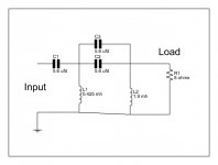
Herewith attached the circuit.
It is linkwitz 4 th order.The inductor values are mentioned on PCB.
I hv not included the L pad circuit.
I hv tested this with DAAS 32 & used 8 ohm resistor as load.
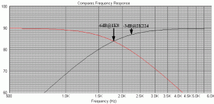
By right quick on graph we come to know the attenuation & frequency.
The graph is linear ( no bump or notch) & proper.
It is linkwitz 4 th order.The inductor values are mentioned on PCB.
I hv not included the L pad circuit.
I hv tested this with DAAS 32 & used 8 ohm resistor as load.
By right quick on graph we come to know the attenuation & frequency.
The graph is linear ( no bump or notch) & proper.
Attachments
Herewith attached the circuit.
It is linkwitz 4 th order.The inductor values are mentioned on PCB.
I hv not included the L pad circuit.
I hv tested this with DAAS 32 & used 8 ohm resistor as load.
By right quick on graph we come to know the attenuation & frequency.
The graph is linear ( no bump or notch) & proper.
As long as the test resistor is non-inductive, the curve should look textbook and be at the predicted crossover frequency (within the tolerances of the components).
However, your speakers (drivers) are not non-inductive resistors.
This is probably why the performance varies so much.
a single pole filter is very tolerant of less accurate components.
You will easily get away with using +-10%
as you add a further pole, the tolerance of components must be tighter.
Most expensive commercial speakers stop at 3pole passive and part of the reason must be the accuracy required of the components.
I can't recall, but there must be some, a speaker with a 4pole passive crossover.
i have not attached the driver to this circuit.
All tests have been carried out with resistor load.
I think that the drift is due to component values as Loren42 say.
The capacitors are +/- 5% & drift is almost more than 15%.
Oh I see, so you didn't test the driver. Then the drift is caused by component "tolerance", but this drift is not a big deal. The real issue is after you connect the drivers where actual impedance is different with nominal impedance.
The big drift you see on your simulation is because you see at -3dB while you should see at -6dB.
The crossover point of different filter not always at -3dB. For example, 2nd-order LR is at -3dB, 4th-order Butterworth is at -3dB, and 4th-order LR is at -6dB.
Attached is a picture of LP and HP slopes of LR4 crossing at 1K8. As you can see, they are crossing at -6dB. If you look at -3dB the corresponding theoretical frequency should be 2K224.
Now you want to compare 2K224 with 2K4 of your measurement. Is that a big deal? No. But if you want to argue, first measure your load resistor. If your load resistor is below 8 Ohm (e.g. 7.9 tho rarely) then you will expect a higher frequency than 2K224.
Attachments
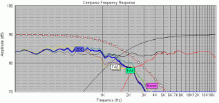
Both LR2 & LR4 have -6dB at the crossover frequency.
That is what the Q=0.5 tells us.
Ah yes, you're right!
Attachments
U means to say that for 4th order -24db, we hv to see -6 db point?
The driver impedance is 8 ohms
Yes you have to see the -6 db point for a linkwitz riley crossover.
- Status
- This old topic is closed. If you want to reopen this topic, contact a moderator using the "Report Post" button.
- Home
- Loudspeakers
- Multi-Way
- 4th order butterworth/linkwitz passive crossover