I'm trying to design a 2 way with a waveguided tweeter, but I'm a bit anxious about the crossover. My first concern is the center to center distance of the woofer and tweeter. Everything I'm looking at building will require this distance to be greater than the wavelength of the crossover frequency in order to get the horizontal directivity at the crossover frequency to match. Best case scenario I'm looking at is about 110% of the wavelength of the crossover frequency. I wonder how this will effect what I hear at 2-3 meters with the middle of the space between the drivers at me listening ears' height? Is there and sims or real world measurements of speakers with varying c to c spacing anywhere on the web? Or of a vertical polar response of a mid/wg or horn combo where c to c spacing is less than the wavelength of the crossover frequency and another where the space is greater?
I have the ability to measure speakers myself, but I can't seem to come up with a clever jig for measuring vertical polar response that will do an accurate job. Has anyone done this or know of an example?
Maybe Pi Speakers will have some info on this as Wayne seems to be the only designers who bothers with vertical polars--which is what begs me to question what effect they will have in room.
In my head it seems a narrow c to c would produce a broader response lobe, but is that good or bad? Seems more broad might create issues from early reflections, too narrow and you'll get response anomalies when you stand up. Thing is I generally don't watch movies standing up.
In any case I'd like to get a neutral intelligent discussion on the stated subject of the thread if there is any interest.
Dan
I'm trying to design a 2 way with a waveguided tweeter, but I'm a bit anxious about the crossover. My first concern is the center to center distance of the woofer and tweeter. Everything I'm looking at building will require this distance to be greater than the wavelength of the crossover frequency in order to get the horizontal directivity at the crossover frequency to match. Best case scenario I'm looking at is about 110% of the wavelength of the crossover frequency. I wonder how this will effect what I hear at 2-3 meters with the middle of the space between the drivers at me listening ears' height? Is there and sims or real world measurements of speakers with varying c to c spacing anywhere on the web? Or of a vertical polar response of a mid/wg or horn combo where c to c spacing is less than the wavelength of the crossover frequency and another where the space is greater?
I have the ability to measure speakers myself, but I can't seem to come up with a clever jig for measuring vertical polar response that will do an accurate job. Has anyone done this or know of an example?
Maybe Pi Speakers will have some info on this as Wayne seems to be the only designers who bothers with vertical polars--which is what begs me to question what effect they will have in room.
In my head it seems a narrow c to c would produce a broader response lobe, but is that good or bad? Seems more broad might create issues from early reflections, too narrow and you'll get response anomalies when you stand up. Thing is I generally don't watch movies standing up.
In any case I'd like to get a neutral intelligent discussion on the stated subject of the thread if there is any interest.
Dan
If I was designing a loudspeaker around a waveguide, I would consider applying FIR filters. A FIR filter should minimize overlap (>96dB/octave) without contributing any phase or amplitude errors.
If I was designing a loudspeaker around a waveguide, I would consider applying FIR filters. A FIR filter should minimize overlap (>96dB/octave) without contributing any phase or amplitude errors.
Seems a bit too complicated for me to even begin contemplating. Interesting idea though. I think we already know why others haven't taken this approach. $$$
Dan
Many comments. SPEAK will model this for you. Its free now. Just go to my web site.
First, the horizontal polars are critical, while the verticals are just "important". Never compromise on the horizontal to solve an "imagined" problem in the vertical.
The spacing and crossover frequency sets the angle between the nulls. The lower the frequency the wider the nulls. There is NOTHING that you can do electrically to alleviate this and very sharp filters have very high phase changes and a whole other set of problems of there own. Basically the nulls are there no matter how sharp the filter is, it doesn't fix the most significant problem, it only creates other ones - like huge cost implications.
Of course closer spacing is always desirable as long as NOTHING is done to degrade the horizontal polars. This is why I don't approve of coax (except in space critical apps.) - no vertical lobes, but lousy horizontal pattern control. Give me a couple of vertical lobes over that any day.
Now, there will be a pair of nulls, up and down, and its best to place them symmetrical about the listening axis. This is not always easy to do, it takes some real effort in the crossover to get the vertical lobes symmetric AND a good match in the horizontal plane. Just getting a good axial response is trivial by comparison.
Thats about the best that you can do, and personally, I find that this situation works just fine.
As a practical example, the Summa has a C-C spacing of about 18 inches, and a crossover at about 800 Hz. The nulls are up and down at about 15-20 degrees. At 3-4 m back this places them at about 1 m up and down from ear level - not a problem. You said 2-3 m so worst case would be .5 m, more likely .75 m, still not a problem. There is an ever so slight dip in the power response at the crossover as a result of this, but nothing significant.
Last edited:
Many comments. SPEAK will model this for you. Its free now. Just go to my web site.
I looked your site over, and must have missed this SPEAK of which you speak. On what page is it located, if I may?
Many comments. SPEAK will model this for you. Its free now. Just go to my web site.
First, the horizontal polars are critical, while the verticals are just "important". Never compromise on the horizontal to solve an "imagined" problem in the vertical.
The spacing and crossover frequency sets the angle between the nulls. The lower the frequency the wider the nulls. There is NOTHING that you can do electrically to alleviate this and very sharp filters have very high phase changes and a whole other set of problems of there own. Basically the nulls are there no matter how sharp the filter is, it doesn't fix the most significant problem, it only creates other ones - like huge cost implications.
Of course closer spacing is always desirable as long as NOTHING is done to degrade the horizontal polars. This is why I don't approve of coax (except in space critical apps.) - no vertical lobes, but lousy horizontal pattern control. Give me a couple of vertical lobes over that any day.
Now, there will be a pair of nulls, up and down, and its best to place them symmetrical about the listening axis. This is not always easy to do, it takes some real effort in the crossover to get the vertical lobes symmetric AND a good match in the horizontal plane. Just getting a good axial response is trivial by comparison.
Thats about the best that you can do, and personally, I find that this situation works just fine.
As a practical example, the Summa has a C-C spacing of about 18 inches, and a crossover at about 800 Hz. The nulls are up and down at about 15-20 degrees. At 3-4 m back this places them at about 1 m up and down from ear level - not a problem. You said 2-3 m so worst case would be .5 m, more likely .75 m, still not a problem. There is an ever so slight dip in the power response at the crossover as a result of this, but nothing significant.
Thank you Dr. Geddes! So the wavelength of 800Hz is about 17inches or about 106% of the crossover frequency wavelength and you're just a touch beyond that with nulls at 15-20 degrees. The best I can do with my design seems to be about 122% of the wavelength at the crossover frequency. Anyone know how to calculate my nulls if I were to build such a thing? I'll model it when I get my windows rig up and running again if it can't be calculated. Seems to me it should be fairly straight forward though.
Right now I'm listening to a speaker that is fairly CD in the horizontal plane, but with a c to c spacing greater than 2x the crossover frequency and I still hear an advantage to CD compared to my direct radiators.
Dan
Last edited:
Speak is here. Also check out John Kreskovsky's article on power response and crossovers. Won't give you any answers but does provide a lot of tools.
My current system is just about two wavelengths at its LR4 2kHz cross. It's perfectly liveable but is definitely happier with a 2.5+m listening distance than at ~2m or lower. The design I'm currently looking into replacing it with would be about 1.3 wavelengths with an LR6 2kHz cross; should try putting that in Speak and seeing what I get.
My current system is just about two wavelengths at its LR4 2kHz cross. It's perfectly liveable but is definitely happier with a 2.5+m listening distance than at ~2m or lower. The design I'm currently looking into replacing it with would be about 1.3 wavelengths with an LR6 2kHz cross; should try putting that in Speak and seeing what I get.
I have the ability to measure speakers myself, but I can't seem to come up with a clever jig for measuring vertical polar response that will do an accurate job. Has anyone done this or know of an example?
Use the same setup as you would for horizontal polar response, except mount the speaker on its side instead of upright.
Use the same setup as you would for horizontal polar response, except mount the speaker on its side instead of upright.
That difficult d/t reflections off the device. I guess there not that critical in this situation b/c all you're looking for is the nulls and precise FR is less critical for performance evaluation. I'll see how it works.
Thanks Don!
Dan
That difficult d/t reflections off the device.
Dan
Could you ellaborate - I don't follow.
For my Iron Lawbreaker, the center to center distance between the 2220A and the 288-16G is ~13 inches and the xover frequency is about 600hz, so that gives nulls that are close to being directly above and below the speaker with virtually no vertical lobing at any normal listening distance. Another cool thing about that is that this considerably improves vertical dispersion control in the octave surrounding 600hz, minimizing overall floor to ceiling boundary reflections down to ~500hz. Result: greater lower midrange clarity in actual listening environments.
Last edited:
Crossover optimization for DI-matched two-way speakers
I usually measure polars with the speaker laying on its back, facing upward towards a microphone on a boom, using a protractor to place the microphone at the desired angles.
My opinion on coverage is that response should be uniform across a horizontal arc of 90 degrees, and uniform across a vertical arc of at least 40 degrees but not more than about 60 degrees. I also think the center of the forward lobe should be roughly along the baffle normal, with the vertical nulls basically equidistant above and below the speaker.
The reason I like this roughly 90x40 to 90x60 pattern is the 90 degree horizontal pattern is very convenient for home placement, making a useful coverage area with nice large seat-to-seat coverage. The desired vertical pattern is large enough to be useful, allowing the listeners to sit in a clean forward lobe at a reasonable listening distance, but small enough to limit ceiling slap at HF.
Related threads:
Last edited:
Could you ellaborate - I don't follow.
The driver will the be close to my lazy susan platform and I will get a reflection that's not actually in the speaker's response. There will be like a 3inch circular arched lip in front of the driver and close to it. I should have made a smarter device, but I'm just learning here. A flat front would have been better that I could set the baffle edge right up to. I'm sure even in my horizontal polars I'll get some reflection. A little is better than a lot. I'm not trying to sell anything with this info.

I got my horizontal polars on the WG, 15" woofer! Best I've measured. Not that that is saying much.
Thanks again Dr. Geddes! I owe you a few.
Dan
I usually measure polars with the speaker laying on its back, facing upward towards a microphone on a boom, using a protractor to place the microphone at the desired angles.
My opinion on coverage is that response should be uniform across a horizontal arc of 90 degrees, and uniform across a vertical arc of at least 40 degrees but not more than about 60 degrees. I also think the center of the forward lobe should be roughly along the baffle normal, with the vertical nulls basically equidistant above and below the speaker.
The reason I like this roughly 90x40 to 90x60 pattern is the 90 degree horizontal pattern is very convenient for home placement, making a useful coverage area with nice large seat-to-seat coverage. The desired vertical pattern is large enough to be useful, allowing the listeners to sit in a clean forward lobe at a reasonable listening distance, but small enough to limit ceiling slap at HF.
Related threads:
Wow! That's a heck of a list. I've got some reading to do. Thanks a million Wayne!
Dan
A flat front would have been better that I could set the baffle edge right up to.
Dan
Ok, thats what I did and I just assumed yours was the same.
Ok, thats what I did and I just assumed yours was the same.
No, I'm going to have to redesign it. I think I may just use Wayne's method here in the near future.
No, I'm going to have to redesign it. I think I may just use Wayne's method here in the near future.
I don't agree with putting the speakers on the ground because its not the correct conditions. The errors are all highly dependent on the loudspeaker systems specifics so they are not tractable. Free field on a stand is a much more accurate way to do things.
Here's a frontal photograph of one of the Iron Lawbreakers with the woofer grill panel removed.
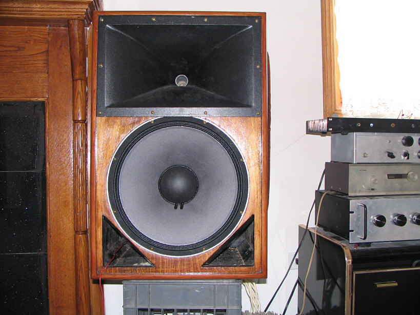
It is easy to see that the center to center distance between the 15.25" diameter bass driver and the horn throat (non diffracting but not HOM optimized either) is less than the diameter of the bass driver itself.
To minimize vertical lobing as much as possible and to try to gain the advantage I described earlier with floor and ceiling reflections, the electrical xover point is set to ~550hz which is lower than normal for this type of horn without the use of high order xovers. However, by adding a xover zero around 300hz (modified elliptical type), both a rapid xover rolloff starting above the ~400hz acoustical cutoff of the horn and a decent approximation of a first order xover phase transition is achieved, when the setback of the 288 G HF driver compared to the 2220A woofer VC and LF quasi first order xover is considered. Without the 300hz notch (i.e. with a straight first order HP xover to the 288G), its audible distortion at higher program levels becomes significant.
It so happens that near this xover frequency, the disperson of the 2220A is beginning to narrow, so a reasonably seamless horizontal as well as vertical integration of each driver's polar response is achieved.
Last edited:
non diffracting ....
I'm sorry, but there is a huge change in the contour from the driver to the horn and a significant amount of diffraction will occur at this point. It is a diffraction horn in my book.- Status
- This old topic is closed. If you want to reopen this topic, contact a moderator using the "Report Post" button.
- Home
- Loudspeakers
- Multi-Way
- Importance of vertical polar response