I have a 12 inch speaker. What it came off of I don't know. I am assuming it is from the tube era. I am guessing by the grill cloth at least 50's era or earlier.
It has a transformer attached to the outer part of the speaker rim, with three connections on the primary and two on the secondary. Actually more on the secondary but only two are used. I am assuming that transformer is made for a push pull amp. The weird thing for me is that it has not only the voice coil but two separate coils on the magnet which is round and about two inches in diameter and about three inches long. Starting with the secondary of the transformer, one side goes to the voice coil directly. The other side of the secondary goes to one of the windings on the magnet and the other side connects back to the other side of the voice coil. My thought is this is a bass speaker and that coil is to change the response of the speaker to the low freq. range by adding inductance. So what is the other coil for? It goes to a harness which at one time went to a plug (still attached) back to the amp. (The amp does not exist). What did it connect to, back at the amp or what is it for? Remember this coil is also wound on the magnet and not another voice coil. I am stumped on this one.
I am sorry about placing thread in wrong place, too late for me to change it.
Last edited:
Anything along these lines,
Mains energised speakers. - UK Vintage Radio Repair and Restoration Discussion Forum
Mains energised speakers. - UK Vintage Radio Repair and Restoration Discussion Forum
Are you sure there is a magnet?
The "other coil" could be a field coil to magnetize the core.
See here for an explanation:
Antique Electronic Supply - Speakers
The "other coil" could be a field coil to magnetize the core.
See here for an explanation:
Antique Electronic Supply - Speakers
Speakers with a field coil rather than a permanent magnet (called "mains energised" in the UK) sometimes had 3 windings:
1.voice coil (a few ohms), 2. field winding ( a few hundred ohms) 3. a hum cancellation winding. I can't remember the resistance of the hum cancellation "dinger" coil.
On this type the field winding would double as a choke in the HT or +B supply. The ripple would cause hum in the speaker which would be cancelled by out-of-phase current though the "dinger" coil". I think the "dinger" coil was on or near the voice coil and was connected in series with the field winding.
We're going a long way back here...
Are you sure there is a magnet?
The "other coil" could be a field coil to magnetize the core.
This is where a picture would be worth a 1000 words.
dave
After a quick google, it seems there are some modern "field winding" speakers.
I wonder if this is the way to go? After all it's easier to produce high quality, high power DC for the field winding, than to produce high quality, high power audio for the voice coil.
In other words: why not increase speaker efficiency by this method, so as amplifier power can be reduced...
I wonder if this is the way to go? After all it's easier to produce high quality, high power DC for the field winding, than to produce high quality, high power audio for the voice coil.
In other words: why not increase speaker efficiency by this method, so as amplifier power can be reduced...
here are some pics
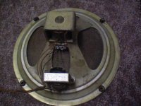
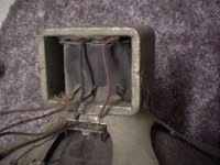
Here are some pics of the speaker. the coils are 2.5 inches across and 2 inches high. The speaker is a 12 inch. It might not be a magnet at all on there as I don't really know. The pics are from camera with 480x640. if you need better resolution the best I can do is 1 meg, but I can get as close as you need.
thanks.
Attachments
Banned
Joined 2002
Here are some pics of the speaker. the coils are 2.5 inches across and 2 inches high. The speaker is a 12 inch. It might not be a magnet at all on there as I don't really know. The pics are from camera with 480x640. if you need better resolution the best I can do is 1 meg, but I can get as close as you need.
thanks.
the transformer might look like it step's up or down voltage to create a magnetic coil,
It's all clear now:
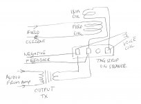
There is a big field coil and a smaller hum coil on the same core. The field coil is fed directly and doubles as a choke. The hum coil is connected in series with the voice coil to cancel some of the AC component.
There is a conventional output matching transformer, it's secondary being connected to the voice coil via the hum coil. Both secondary connections are sent back to the amp for negative feedback.
Attachments
yeah that's it. Do you know of a piece of equipment that uses this that I may find a schematic on? I am unclear what provides the field coil current. Is it just a mains and if so what at what voltage and should it be current limited? This is a first for me, not new at electronics though, still learning after 43 years of playing with the stuff. Thanks for the replies.
I might have know once. It was typical of the "junk" my dad used to bring home from work for me to tinker with in my school days - and I'm close to retirement now...yeah that's it. Do you know of a piece of equipment that uses this that I may find a schematic on? I am unclear what provides the field coil current. Is it just a mains and if so what at what voltage and should it be current limited? This is a first for me, not new at electronics though, still learning after 43 years of playing with the stuff. Thanks for the replies.
The field coil will have been connected in place of a smoothing choke. That puts it after the rectifier valve/tube and with the main reservoir cap on the other side. That point will have been connected to one side of the output transformer.
- Status
- This old topic is closed. If you want to reopen this topic, contact a moderator using the "Report Post" button.
- Home
- Loudspeakers
- Multi-Way
- need help with figuring out the connections on an old speaker