Allrighty then. I'm only confusing myself it seems.
What would be the purpose of confining horizontal to 100deg,
but then let the vertical flip over a thin edge and fill in the very
quadrants I had excluded??? My thin lip plan ain't gonna work.
Seems I'm gonna need a baffle wide enough that the lowest
note of the horn can't get easily around it. Confining Vertical
to 180 or preferably much less (if thats possible).
I'm not too worried bout high order modes in the parts of the
waveguide that are less wide than the cutoff frequency of
those modes. Even in the horizontal, there are plenty of foam
septums that deny those modes. But one we bust loose from
the front slot, then things get HOM right quick like. But only
if there is something nearby to bounce on.
So maybe I want a wide flat (barrel faced) lip? But this flies
in the face of wanting the plate lens termination Kuts for 3
reasons stated before (K loading, plate lensing, smearing the
time of reflections back down the throat from the abrupt lip.)
I don't know that I can accomplish the K-Kut without giving
the diffracted wave front unwanted semi-parallel surfaces to
bounce between? Thus setting myself up for a mess of the
High order modes...
Geddes might be right, but I'm not ready to bail out just yet.
Sometimes things that aren't "supposed" to sound good, do.
And its not an experiment likely to eat up a lot of resources.
I'm still also in a quandry bout the right shape for the plate
lenses. Exponential scallops as drawn in post #7 seems the
right lens for K loading. But taking bites from the edge of a
big cookie the better lens for correcting horizontal beaming.
A triangular sawtooth would be the compromise scallop cut,
and also perhaps minimally parallel to itself??? But presents
sharp triangle corners for curiosity seekers to put an eye out.
Maybe not such a hazard if the scallops are also fairly tall???
But then do the leading edges of such triangular scallops then
present new diffractions??? Or does their vertical orientation
exclude them from being seen by the wavefront as it passes?
So much for keepin it simple, eh?
Last edited:
If you want the field emerging from the horn to map to the field in the listening position then the two fields must be potential fields, that is all vectors point towards a point or a line.
If the device produces a spherical wave then this is defined by a potential field since all vectors appear to come from one point.
When such a wave leaves the inside of the device however if the transition is abrupt then
the field produced is the result of the superposition of two fields that do not sum to a third potential field; all schemes featuring large amounts of diffraction do this.
A field that does is one in which the apparent sources are a coplanar point and annulus, a o.s. horn with a circular arc mouth section has this property, so does the type of dome driven devices I have described.
A very useful tool to aid in visualization of this is Axidriver.
rcw.
Sometimes things that aren't "supposed" to sound good, do.
This is the crux of the matter - the part that I disagree with.
Everything that I do is done because "it's supposed to" be right and after some 30 years I'm still doing the "right" thing and ignoring that which defies logic - the audiophile dogma. I havn't found reason to question my position and accept the statement above.
Check out my "Homster" thread:
http://www.diyaudio.com/forums/multi-way/151376-homster-how-i-learned-how-fix-horn-6.html
In the thread above I demonstrated how to improve the sound of a horn that's way too wide for it's own good. Here are some quick observations, based on the experiment:
- Even with tons of work, my oblate spheroidal waveguides sound much more natural than the horns from this experiment
- After modification, the USD horns measure surprisingly good. IMHO, the reason that the USD horns work as well as they do is because they have a diffraction slot in the throat. That slot appears to be critical in creating a semblance of constant directivity
- I built horns which are somewhat similar to the USD horns, but my horns do NOT have a diffraction slot. While they are dynamic and sound quite good, my own measurements demonstrate that the USD horns are closer to constant directivity. Again, I think this is due to the diffraction slot
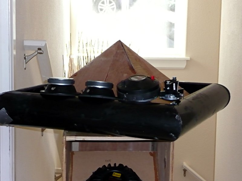
- I think you can see where I'm going here... Mouth treatment is very important. It won't turn a sow's ear into a silk purse, but it's as close as we can get. Here's a pic of my latest horn. You can see I went buck wild with the roundover at the mouth.
Last edited:
I've only one graph of a 1" Smith Horn with Peavey 22A - enjoy or critique the thing for what is ..
An externally hosted image should be here but it was not working when we last tested it.
Diffractions far enough back in the throat could not themselves be causing HOMs.
Where throat is significantly less than 1/2 wavelength in width, high order modes
are in cutoff, and cannot be sustained. At 1/4 Wave width and less, the dominant
mode that is likely to propagate is only the plane or spherical wave front...
Now you can have a standing wave from any discontinuity back to the driver that
has sort of a mode I suppose??? But follows the same rules. Within 1/4 wave of
the driver, high order standing waves are already well suppressed by FCO.
The mouth of a horn is another story. Here most waveguide is plenty wide enough to
support high order modes when touched off by diffraction. As-is the standing wave
distance back to the driver... But the Smith horn (even in its original design)
has only the latter of these two problems. And I think that problem is managable.
I describe a system that perhaps defies easy analysis and/or simple simulation.
But nothing here that defies logic or physics, except my grammar and punctuation.
And maybe styrofoam, yes now styrofoam I can see how it defies logic and physics
and hopefully federal statutes as well! Well, we can hope anyways...
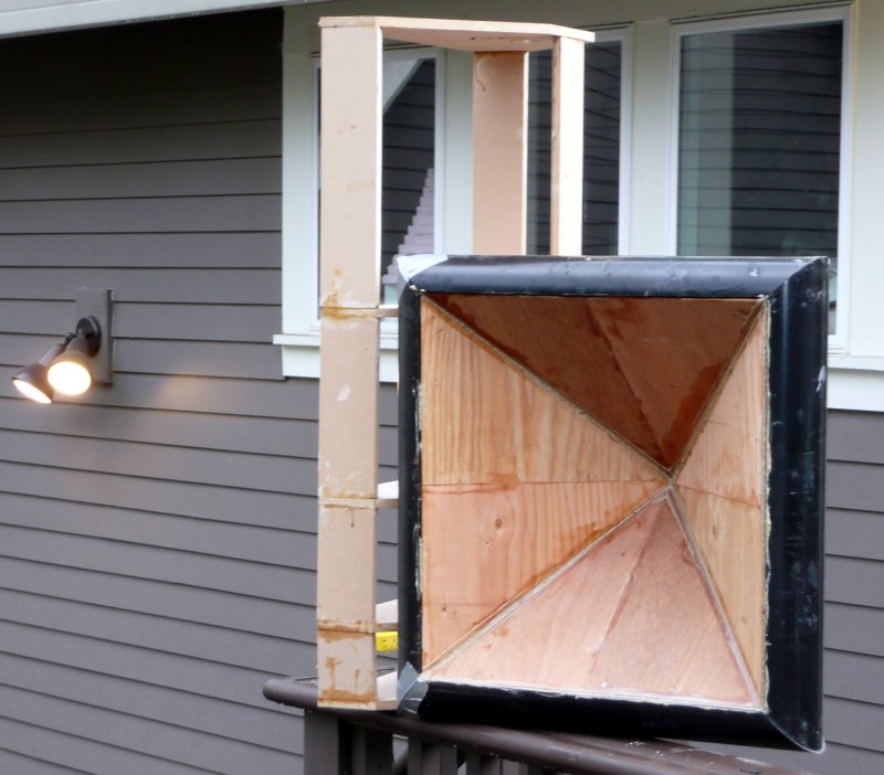
Supposin I had a 90deg Smith horn, with thin lips, turned backwards? And firing
up at a slight angle toward a curved reflector (just enough angle that most of
the reflection is above the lip, and not back into the mouth of the horn). Now
I think I am back to covering only 1 horizontal quadrant again? The problem of
diffraction curlback into unwanted quadrants is solved by cooperating with it???
If I choose to scallop the lips, I don't think that is gonna HOM anything. And
turned backwards will keep eyes from being poked out if I choose the cookie or
triangle lens cuts.
I'm sure both the top and bottom edges of said reflector and the back end of the
horn facing toward the audience will need to be blended to prevent new unmanaged
diffractions, else we are back to the HOMsville we just escaped from.
Whats supposed to be the benefit of all this complexity over Geddes simple and
admittedly effective solution? Exponential loading, thats about all I can think
of... So maybe not worth the trouble? But again, not an expensive experiment,
as the curved reflector can be hacked out of concrete forming tube...
Where throat is significantly less than 1/2 wavelength in width, high order modes
are in cutoff, and cannot be sustained. At 1/4 Wave width and less, the dominant
mode that is likely to propagate is only the plane or spherical wave front...
Now you can have a standing wave from any discontinuity back to the driver that
has sort of a mode I suppose??? But follows the same rules. Within 1/4 wave of
the driver, high order standing waves are already well suppressed by FCO.
The mouth of a horn is another story. Here most waveguide is plenty wide enough to
support high order modes when touched off by diffraction. As-is the standing wave
distance back to the driver... But the Smith horn (even in its original design)
has only the latter of these two problems. And I think that problem is managable.
I describe a system that perhaps defies easy analysis and/or simple simulation.
But nothing here that defies logic or physics, except my grammar and punctuation.
And maybe styrofoam, yes now styrofoam I can see how it defies logic and physics
and hopefully federal statutes as well! Well, we can hope anyways...
Supposin I had a 90deg Smith horn, with thin lips, turned backwards? And firing
up at a slight angle toward a curved reflector (just enough angle that most of
the reflection is above the lip, and not back into the mouth of the horn). Now
I think I am back to covering only 1 horizontal quadrant again? The problem of
diffraction curlback into unwanted quadrants is solved by cooperating with it???
If I choose to scallop the lips, I don't think that is gonna HOM anything. And
turned backwards will keep eyes from being poked out if I choose the cookie or
triangle lens cuts.
I'm sure both the top and bottom edges of said reflector and the back end of the
horn facing toward the audience will need to be blended to prevent new unmanaged
diffractions, else we are back to the HOMsville we just escaped from.
Whats supposed to be the benefit of all this complexity over Geddes simple and
admittedly effective solution? Exponential loading, thats about all I can think
of... So maybe not worth the trouble? But again, not an expensive experiment,
as the curved reflector can be hacked out of concrete forming tube...
Last edited:
Well, yeah. Go tall thats the answer if I choose a smooth unscalloped circular lip.
But thats still also reflection (from the sudden transition) all equidistant from the
throat. I was wanting lens termination cut partly to avoid that reflection setting
a standing wave back down the throat(s). Flies in the face of a smooth (but tall)
barrel faced circular lip.
Mabey if I creased the poster board to follow the sectoral lenses? But then I am
also maybe setting up semi-parallel surfaces at distances wide enough for HOM.
But this is all surfaces perpendicular to the lip and wavefront, so still might not
be a total HOMster... or would it...???
Curved refector (even if made of the same poster board) lets me keep the plate
lens lip thin and short. Theoretically giving much less parallel surfaces for HOMs
to form. but is this any better than a forward Smith with lenses and tall poster
lips? I just don't know without trying...
Last edited:
Diffractions far enough back in the throat could not themselves be causing HOMs.
...
The mouth of a horn is another story. Here most waveguide is plenty wide enough to support high order modes ...
Admittedly sounds logical. But the situation has to transition, it can't be that HOMs don't exist and then all of a sudden they do. Its this transition that matters.
There is no answer to this question.Its not the "slot" that diffracts, its the edges.
Thats one of the major problems.
Not much is going to help with a mouth shaped like that.
There is no such thing as "good" diffraction. It's all bad in a playback system and so I never considered exploring what you suggest since its obvious that there isn't a "right" way to do the "wrong" thing.
Since diffraction happens at the edges, there may be a couple worthwhile improvements:
1) be sure to put the horn on a surface that extends the curve. For instance, if it was mounted on the ceiling, or on a large flat surface
2) big fat roundovers work wonders
- Status
- This old topic is closed. If you want to reopen this topic, contact a moderator using the "Report Post" button.
- Home
- Loudspeakers
- Multi-Way
- Styrofoam Smith Horn