Earl, I'm curious about the "has to be Shore A" bit. I can't tell if you mean this literally, or simply that Innovative's other option - Shore D - is the wrong choice of these specific 2.Try Innovative Polymers, Inc. | IE Series™ Urethane Liquid Plastic :: Shore A
That's what I use. It has to be Shore A.
If you had to choose a different product line, would you consider Shore OO or other scales? Or does Shore A cover the sweet spot of a curve, giving maximum performance here?
Also, there are a number of Shore A options in your link, from 10 to 80. Any preferences in there? I'd assume that softer would be better - especially with the microspheres added - but your experience is probably a bit better than my assumption.
")
Thank you!
Third time is the charm, hopefully...
Do you mean this? See below.
Thank you. What should I be looking at exactly? Maximum tensile and tear strength? If so the IE-80A seems excellent.
I'm not sure what it attached to what, it may be correct. Think of it as six pistons in six cylinders; the piston rods are all attached together; the cylinders to the walls. The gap is the CLD material, fairly thin. This will dampen all modes of the cabinet, especially LF ones.
I used IE40, of what was available 20 years ago, it worked the best. Today anything is possible, it just takes some experiments (and good analysis of same.)
Who needs evidence? Common sense and experience shows that both would happen.
To perhaps take a step back from this argument, let me say that I would always assume the the enclosure is heavily damped inside, which means that pretty much only LFs below say 200 Hz are going to make it through this damping and back, but below that, of course they are felt by the cone. But the cone is not only a dead mass to a sound wave, it's well damped, but these sound waves will be felt and will modify the cones movement to the extent that they are significant.
In my case when the speaker was measured with and without its enclosure back (on axis of course.) I could not detect any differences once the box compliance (a direct result of these enclosure "reflections") and dipole effect was adjusted for. My only conclusion had to be that these internal reflections are not coming back through the cone to a significant degree.
To me, that's evidence to the contrary of your position.
Hmm, I think I might have trouble visualising what you're trying to describe.I'm not sure what it attached to what, it may be correct. Think of it as six pistons in six cylinders; the piston rods are all attached together; the cylinders to the walls. The gap is the CLD material, fairly thin. This will dampen all modes of the cabinet, especially LF ones.
I used IE40, of what was available 20 years ago, it worked the best. Today anything is possible, it just takes some experiments (and good analysis of same.)
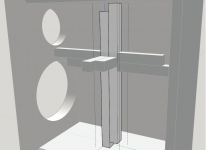
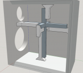
Below I show every brace (doubled) that goes through each other and as such will be connected to each other in the middle.
If I interpreted it wrong, would you mind drawing it for me, or show an example?
Attachments
In free SketchUp, all you do is push and pull a surface to create 3D objects.
It is very easy to use if you have a 3D mouse to navigate.
Ahhh.... but the first time using it can be a slow process. A person could easilly spend 45 minutes learning to make a simple drawing of a box. I understand Earl's position.
Arnandsway,
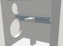
Earl said to have a cross in the center, then connect the arms of the cross to the panel using shear method.
Instead of having 2 long pieces going side to side, you need 2 short pieces that connect to the cross.
Earl,
you said 1" oak is strong enough for cross bracing.
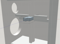
If we use 1" stick, is the 1" wide strip of shear enough?
How big is a shear area enough?
Earl said to have a cross in the center, then connect the arms of the cross to the panel using shear method.
Instead of having 2 long pieces going side to side, you need 2 short pieces that connect to the cross.
Earl,
you said 1" oak is strong enough for cross bracing.
If we use 1" stick, is the 1" wide strip of shear enough?
How big is a shear area enough?
Not sure whether some comments on the engineering are welcome or not so please feel free to ignore.
If the struts are being used as damping panels the strength and stiffness of the wood is pretty much irrelevant. The stiffness of the structural bracing is determined by the stiffness of the damping layer which is pretty much nothing. The main effect will be to add mass to the centre of the panel which will lower resonant frequencies and require more damping material to damp effectively and, obviously, to introduce some local (not global) damping to the motion of the cabinet exterior.
Thin rods are not the usual the shape for damping panels because they shear relatively little material. A damping panel will usually seek to have a large area between the wood and the damping material.
The cross arrangement above will not damp all relevant modes. It won't damp any modes where the opposite panels move together rather than in opposite directions, it won't damp any 2nd order mode shapes with a node in the centre, it will only weakly damp the lowest motions (e.g. a nodding mode) which do not involve significant movement between the centres of opposite panels, etc...
To be a bit more positive it will introduce some damping which is good but the effectiveness will be largely unknown without knowing which modes are the loudest at the listening position. Not all modes are effectively driven and of those that are not all will radiate loudly at the listening position. Without knowing the problematic mode shapes the location of the largest relative cabinet motion is unknown and hence where to locate the ends to introduce effective local damping.
In the presence of a reasonable amount of global damping (i.e. more than the low amount present in wood but nothing excessive) there are likely to be few modes and possibly only one that would benefit from some targeted local damping. A mode with the low frequency driver bouncing on the baffle is likely to be problematic because it is normally low in frequency, is efficiently driven and radiates strongly at the listening position. The others for this cabinet are?
Given the drawings above show a smallish speaker with thick walls conventional CLD applied to the 5 non-baffle panels would seem an effective way to introduce significant levels of global damping (e.g. 12-15 mm structural layer, 2 mm damping and 6 mm constraining layer). How worthwhile internal structural bracing and any possible internal damping panels might be is not immediately apparent (to me) without further consideration.
The baffle has different requirements to the 5 sides. The stiffer the baffle the lower the amount of energy put into vibrating the cabinet by the drivers. Once energy is in the cabinet structure then damping of all 6 sides will act to dissipate it and the more damping the better. The stiffness:damping trade-off for the baffle is different to that for the sides with it leaning significantly more strongly in favour of stiffness.
Last edited:
4th time the charm?I can't tell what is attached to what in your drawing. If you start as I suggested, you should be able to evolve it to square rods. I just don't have access to good drawing tools (and I am not about top learn now.)
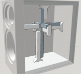
I made the cross brace in blue so you can see that the other legs/fingers (in white) are connected to the panels.
I also widened the connecting surfaces of the legs. Because in my thinking this would make it more rigid. Hopefully it isn't too confusing.
Attachments
Last edited:
That's a lot clearer. How would the middle of the blue cross brace(s) (of the legs) be connected together? Are they glued as well or connected together with screws or the like?
4th time the charm?
I made the cross brace in blue so you can see that the other legs/fingers (in white) are connected to the panels.
I also widened the connecting surfaces of the legs. Because in my thinking this would make it more rigid. Hopefully it isn't too confusing.
Yea, that's right. The brace needs to be "rigid enough", but rigidity is not what you want, it's damping. The Shore hardness will determine the stiffness far more that the legs or the attachment. So personally, I would just use straight legs, no flare. I don't see it doing anything.
The piston/cylinder analogy Earl wrote would have 4 times the shearing area than two rods side by side like you've modeled. Piston/cylinder approach raises questions like: How to make the cylinders, plywood? how to assemble the actual box with construction like that?
I don't actually use tubes, I use square rods just like shown.
I make the piece separately and glue it in after the enclosure is assembled.
Overkill is not good engineering.
I make the piece separately and glue it in after the enclosure is assembled.
But my piece is only a cross in 2D, not 3D, so placing it isn't a problem. With a 3D one that could be tricky. In my speakers I only damp the front-back and sides. Top and bottom are pretty small and one in on the ground, so I don't worry about those.
An interested reader with a question. If I understand correctly the pieces are glued along the long axis, the point where they intersect in the middle of the enclosure and glue at the ends where they touch the walls of the enclosure.
And it's not glue but this IE40 damping material?
Thanks
David
And it's not glue but this IE40 damping material?
Thanks
David
Yes, the IE40 is applied all along the braces. I usually use a hard glue to attach them to the walls, and a hard glue at the center. But no where should one be able to follow a path through any hard mount from any side to any side or the middle joint. All path must be damped.
Here is the thing with IE40, it is very thin and runs out all over. The filler helps - a lot - but it still runs. So I ended up making a mold that I could basically cast the pieces into thus filling up and coating all the surfaces. This was about the best method that I found. The piece when it was done was dead, dead, dead.
- Home
- Loudspeakers
- Multi-Way
- constrained layer damping with MDF and Ply